


4
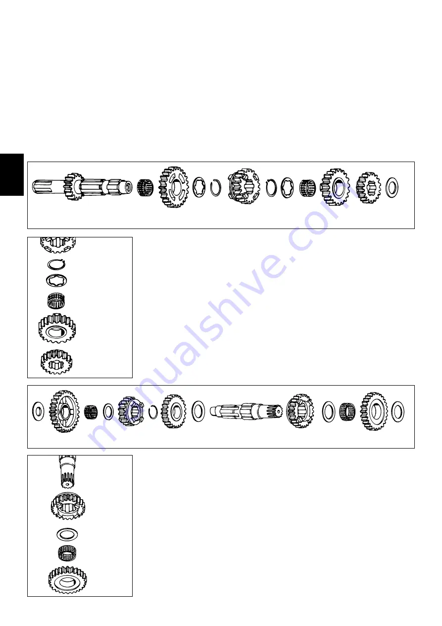
4.15.1 Assembly mainshaft
– Fix mainshaft in vice with toothed end upwards (use covered clamps).
– Oil all parts before assembly.
– Mount the split needle cage
1
on mainshaft, push 5
th
idler gear
2
over it with collar downwards.
– Place internally toothed stop disc
3
in position and mount circlip (25x1.64 mm)
4
with sharp
edge upwards.
– Place 3
rd
sliding gear
5
in position with shift groove downwards, mount circlip
6
with sharp edge
downwards and internally toothed stop disc
3
.
– Mount the split needle cage
1
, 4
th
idler gear
7
with shift dogs downwards 2
nd
gear
8
with collar
downwards and stop disc
9
(20.2x32x1.5 mm).
– Finally check all gears for easy running.
4.15 Transmission
Secure mainshaft or countershaft in the vice (using soft jaw-covers).
Remove gears and check the following for wear:
A
) N
EEDLE BEARING
B
) M
AINSHAFT AND COUNTERSHAFT PIVOT POINTS INCLUDING IDLER GEARS
C
) S
HIFT DOGS AND GEAR WHEELS
D
) T
OOTH FACES OF ALL GEARS
E
) T
OOTH PROFILE OF MAINSHAFT AND COUNTERSHAFT AND CORRESPONDENDING GEARS
F
) E
ASY OPERATION OF GEAR
-
CHANGE
Carefully clean components and replace damaged components.
NOTE
: A
LWAYS PLACE CIRCLIPS WITH SHARP EDGE FACING THE COMPONENTS SECURED
,
ENSURING THAT THEY ARE
NOT OVEREXPANDED
(
USE SPECIAL PLIERS
). C
HECK THAT AFTER ANY REPAIR OF THE TRANSMISSION
,
CIRCLIPS
SHOULD AXIALLY NOT MOVE MORE THAN
0,2
MM
(0.006
IN
)
AND MUST NOT SEIZE BETWEEN STOP DISCS
.
4.15.2 Assemble countershaft
– Fix countershaft in vice with toothed end (use covered clamps).
– Oil all parts before assembly.
– Push stop disc
1
(25,2x40x1,5 mm) onto countershaft.
– Mount 3
rd
idler gear
3
with shift dog recesses upwards and circlip (25x4 mm)
4
with sharp edge
upwards.
– Mount 5
th
sliding gear
5
with shift groove downwards, stop disc
6
(24,2x36x1,5 mm), needle
cage
2
, 1
st
free gear
7
with shift dog recesses downwards and stop disc
8
(17,2x34x1,5-2 mm)
with collar upwards on the countershaft.
– Remove countershaft from vice and fix again with toothed end upwards.
– Mount 4
th
sliding gear
9
with shift dog upwards, stop disc
bk
(28,2x42x1,5 mm), needle cage
bl
, 2
nd
idler gear
bm
with shift dog recesses downwards and stop disc
bn
(25,2x40x1,5 mm).
– Finally check all gears for easy running.
91
0
1
1
1
2
1
2
3
4
5
6
3
1
7
8
9
3
1
9
10
11
12
13
4
5
6
2
7
8
Summary of Contents for 250 1998
Page 9: ... Notices ...
Page 39: ... Notices ...
Page 43: ... Notices ...
Page 44: ...7 1 7 0 Trouble shooting Cap Component Component unit Page 7 1 Trouble shooting 7 2 ...
Page 47: ... Notices ...
Page 54: ......
Page 55: ......
Page 56: ......
Page 57: ......
Page 58: ......


