


-32-
3 Making RS-485/422 Connection
EIA-485
[TIA-485] Balanced (differential) interface; defines the Physical
layer, signaling protocol is not defined. EIA-485 specifies bidirectional,
half-duplex data transmission. Up to 32 transmitters and 32 receivers may
be interconnected in any combination, including one driver and multiple
receivers (multi-drop), or one receiver and multiple drivers.
EIA/TIA-422
define a Balanced (differential) interface; specifying a single,
unidirectional driver with multiple receivers (up to 32). RS-422 will sup-
port Point-to-Point, Multi-Drop topology, but not Multi-Point [EIA485].
EIA-485 devices may be used in 422 circuits, but EIA-422 may not be
used in 485 circuits (because of the lack of an Enable line).
The published TIA/EIA 485 and RS-422 standards define only the electri-
cal characteristics of the drivers and receivers as listed below. They did
not standardize such things such as cables and connectors, pinouts, bus
arbitration, signaling protocols, or physical wiring topology. Many dif-
ferent implementations have come into use and they are often incompat-
ible with each other.
Characteristics
RS-422
RS-485
Mode of operation
Differential
Differential
Unidirectional
Full Duplex
Multipoint
Multipoint
Allowed no. of Tx and Rx
1 Tx, 10 Rx
32 Tx, 32 Rx
Maximum cable length
4000ft length
4000ft length
Maximum data rate
10Mbps
10Mbps
Minimum Tx driver output range
+/- 2V
+/- 1.5V
Maximum Tx driver output range
+/- 5V
+/- 5V
Maximum Tx short-circuit current 150mA
250mA
Tx load impedance
100
54
Rx input sensitivity
+/- 200mV
+/- 200mV
Maximum Rx input resistance
4k
12k
Rx input voltage range
+/- 7V
-7V to +12V
Rx logic high
>200mV
>200mV
Rx logic low
<200mV
<200mV
Summary of Contents for KSC-240
Page 1: ... 1 Industrial RS 232 to RS 485 422 Converter KSC 240 InstallationGuide DOC 070412 KSC 240 ...
Page 7: ... 7 1 2 Specifications This figure shows the important components of the device ...
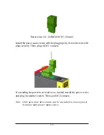
Page 15: ... 15 The final mechanical dimensions after installingDINrail mounting bracket are ...
Page 17: ... 17 The screw locations and final dimension are shown below ...