KT&C EZHD-TRF16 User Manual Download Page 57

User Manual of Digital Video Recorder User Manual 


57 

Figure 4. 11


PTZ Panel - One-touch 


3.


Click 

Linear Scan 

button to start the linear scan and click the Linear Scan button again to stop it. 

You can click the 

Restore

 button to clear the defined left limit and right limit data and the dome needs to reboot to make settings take 

effect. 

4.2.9


One-touch Park 

Purpose: 

For some certain model of the speed dome, it can be configured to start a predefined park action (scan, preset, patrol and etc.) automatically 

after a period of inactivity (park time). 

Steps: 

1.


Click the button 

PTZ

 in the lower-right corner of the PTZ setting interface; 

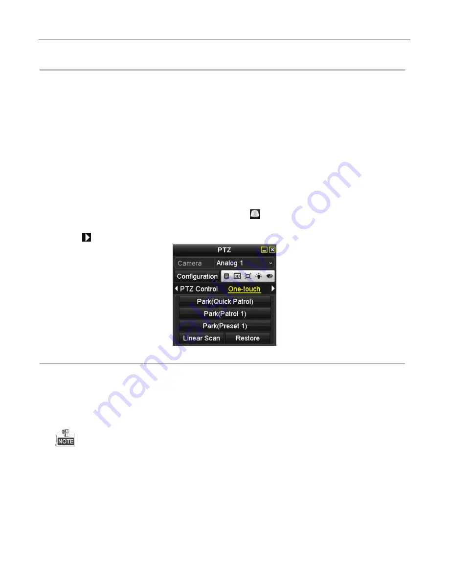
Or press the PTZ button on the front panel or click the PTZ Control icon 

  in the quick setting bar to enter the PTZ setting menu 

in live view mode. 

2.


Click the 

  button to show the one-touch function of the PTZ control. 


Figure 4. 12


PTZ Panel - One-touch 


3.


There are 3 one-touch park types selectable, click the corresponding button to activate the park action. 

Park (Quick Patrol):

 The dome starts patrol from the predefined preset 1 to preset 32 in order after the park time. The undefined 

preset will be skipped. 

Park (Patrol 1): 

The dome starts move according to the predefined patrol 1 path after the park time. 

Park (Preset 1): 

The dome moves to the predefined preset 1 location after the park time. 


The park time can only be set through the speed dome configuration interface, by default the value is 5s.


4.


Click the button again to inactivate it. 

Summary of Contents for EZHD-TRF16

Page 1: ...Triple Technology Recorders 960H EZHD IP EZHD TVL4 EZHD TVL8 EZHD TVL16 EZHD TRF4 EZHD TRF8 EZHD TRF16 User Manual...

Page 2: ...nterference received including interference that may cause undesired operation EU Conformity Statement This product and if applicable the supplied accessories too are marked with CE and comply therefo...

Page 3: ...ecommended A factory recommended HDD should be used for this device Improper use or replacement of batteries may result in risk of explosion or other hazards Replace batteries with the same or equival...

Page 4: ...firmware Please consult the KT C website for updated firmware and descriptions of new features and functions which may have been added via new firmware releases This manual may contain inadvertent te...

Page 5: ...deo exception alarm and video loss alarm functions Privacy masking Several PTZ protocols are supported including PTZ preset patrol and pattern Zoom in out by mouse click and PTZ movement by dragging m...

Page 6: ...or and HDD full etc Alarms can trigger full screen display audio alarm notification to CMS PC sending email and alarm output for models with alarm I O Automatic restore when system returns to normal O...

Page 7: ...shutdown Supports upgrading via remote FTP server RS 485 transparent channel transmission Alarm and exception information can be sent to CMS PC Remotely start stop recording Remotely start stop alarm...

Page 8: ...3 Adding Connecting OMNI IP Cameras 32 2 3 1 Adding Online OMNI IP PnP Cameras 32 2 3 2 Editing the Connected IP Cameras and Configuring Customized Protocols 35 Chapter 3 Live View 37 3 1 Introductio...

Page 9: ...File Protection 76 Chapter 6 Playback 78 6 1 Playing Back Record Files 79 6 1 1 Playing Back by Channel 79 6 1 2 Playing Back by Time 81 6 1 3 Playing Back by Event Search 83 6 1 4 Playing Back by Ta...

Page 10: ...nfiguring Server and HTTP Ports 137 9 2 10 Configuring HTTPS Port 137 9 2 11 Configuring Email 139 9 2 12 Telnet Settings 140 9 3 Checking Network Traffic 142 9 4 Configuring Network Detection 143 9 4...

Page 11: ...Firmware 171 12 5 1 Upgrading by Local Backup Device 171 12 5 2 Upgrading by FTP 171 12 6 Restoring Default Settings 172 Chapter 13 Others 173 13 1 Configuring RS 232 Serial Port 174 13 2 Configuring...

Page 12: ...User Manual of Digital Video Recorder User Manual 12 Chapter 1 Introduction...

Page 13: ...tton is used to speed up and slow down recorded video In All day Playback mode the Left Right button can be used to select the recorded video for the next previous day in Playback by Normal Video Sear...

Page 14: ...READY Ready indicator is normally green indicating that the DVR is functioning properly STATUS Indicator turns green when DVR is controlled by an IR remote control with the address from 1 254 Indicato...

Page 15: ...2 button can be used to cycle through tab pages 4GHI ESC Enter numeral 4 Enter letters GHI Exit and back to the previous menu 5JKL EDIT Enter numeral 5 Enter letters JKL Delete characters before curso...

Page 16: ...ote control closely resemble the ones found on the front panel Refer to Table 1 1 they include Table 1 1 Description of the IR Remote Control Buttons No Name Description 1 POWER Power on off the devic...

Page 17: ...led batteries properly in the remote control You must aim the remote control at the IR receiver in the front panel If there is no response after you press any button on the remote follow the procedure...

Page 18: ...list from your provider The operation of the mouse Table 1 2 Description of the Mouse Control Name Action Description Left Click Single Click Live view Select channel and show the quick set menu Menu...

Page 19: ...Keyboards Description of the buttons on the soft keyboard Table 1 1 Description of the Soft Keyboard Icons Icons Description Icons Description Indicates lower case click to change Indicates Caps click...

Page 20: ...automatically 2 AUDIO IN RCA connector Line in 3 AUDIO OUT RCA connector Line out 4 VGA DB15 connector for VGA output Displays local video output and menu 5 HDMI HDMI video output connector Displays l...

Page 21: ...1 6 EZHD TRF Rear Panels For EZHD TRF models the rear panel vaires primarily in terms of the number of BNC camera inputs Openings for 16 BNCs exist unused openings are closed with plastic covers Descr...

Page 22: ...for alarm inputs Connectors 4 for alarm outputs 10 Power Supply AC 100 240V power supply 11 Power Switch Switch for turning power on off hard power off 12 GND Ground 13 LINE IN BNC connector for two w...

Page 23: ...If you connect an AC load to the alarm output 3 of the DVR then you must remove the jumper JP 3 1 8 Alarm Connection To connect alarm devices to the DVR 1 Disconnect pluggable block from the ALARM IN...

Page 24: ...k 2 Press and hold the orange part of the pluggable block insert signal cables into slots and release the orange part Ensure signal cables are in tight 3 Connect A on PTZ to T on terminal block and B...

Page 25: ...User Manual of Digital Video Recorder User Manual 25 Chapter 2 Getting Started...

Page 26: ...UPS be used in conjunction with the device 2 Turn on the power switch on the rear panel and the Power indicator LED should turn on indicating that the unit has begun to start up 3 After startup the Po...

Page 27: ...system is shutting down The device remains standby mode after shutting down and the POWER indicator turns red you can turn on the device by pressing the POWER button on the remote control Rebooting t...

Page 28: ...list as desired Figure 2 3 Language Selection 2 The Setup Wizard can walk you through some important settings on the DVR If you do not want to use the Setup Wizard at this time click the Cancel button...

Page 29: ...to avoid security issues 5 To change the admin password check the New Admin Password checkbox Enter the new password and confirm the password in the given fields 6 Click the Next button to enter the d...

Page 30: ...twork parameters which will take you to the Advanced Network Setup Wizard window as shown in Figure 2 8 Figure 2 8 Advanced Network Configuration 9 Set the parameters of port No Auto UPnP or DDNS if r...

Page 31: ...click the Init button Initialization will remove all the data saved in the HDD 12 Click Next button to enter the Record Settings window as shown in Figure 2 10 Figure 2 10 Record Settings 13 Click Co...

Page 32: ...e DVR s connection list Before you start Ensure the network connection is valid and correct For detailed checking and configuration of the network please see Chapter 9 1 9 3and 9 4 For an EZHD TVL4 on...

Page 33: ...ne IP cameras Table 2 1 Explanation of the icons Icon Explanation Icon Explanation Edit basic parameters for the camera Add the detected IP camera The camera is connected The camera is disconnected yo...

Page 34: ...2 Steps 1 Enter the Camera Management interface Menu Camera Camera Figure 2 14 Main Menu 2 Repeat the step 3 and 4 of OPTION 1 to add the camera Figure 2 15 IP Camera Management Interface Table 2 2 Ex...

Page 35: ...ps 1 Click the icon to edit the parameters you can edit the IP address protocol at this time only IPCAM is supported and other parameters Figure 2 16 Edit the Parameters Channel Port If the connected...

Page 36: ...nual 36 Figure 2 17 Network Configuration of the Camera 2 You can edit the network information and the password for the camera Figure 2 18 Password Configuration of the Camera 3 Click Apply to save th...

Page 37: ...User Manual of Digital Video Recorder User Manual 37 Chapter 3 Live View...

Page 38: ...s In the live view mode there are icons at the top right of the window for each channel showing the status of recording and alarms for the channel so that you can know whether the channel is recording...

Page 39: ...s means if the HDMI or VGA is used it will be the default main output If the HDMI VGA is not used the CVBS output will be the main output See the table below NOTE The HDMI and VGA images displayed are...

Page 40: ...l channels Normal Record and Motion Detection Recording are selectable from the dropdown list Add IP Camera A shortcut to enter the IP camera management interface Quick Set Output Mode is configurable...

Page 41: ...r Auto PTZ Control The shortcut to enter the PTZ control interface Main Monitor Enter Main operation mode In the live view mode of the main output monitor the menu operation is not available while Aux...

Page 42: ...ecord Instant Playback Mute Audio on PTZ Control Digital Zoom Image Settings Close Live View Instant Playback only shows the recorded video from the last five minutes If no recorded video is found it...

Page 43: ...rer and sharper The degree of contrast and saturation is high Figure 3 5 Image Settings You can adjust the image parameters including brightness contrast saturation hue sharpness and de noising You ca...

Page 44: ...oding is supported as an option Steps 1 Enter the Live View Settings interface Menu Configuration Live View 2 Select the Channel Zero Encoding tab Figure 3 6 Live View Channel Zero Encoding 3 Check th...

Page 45: ...enus Choices are HDMI VGA and CVBS for EZHD TRF models only Live View Mode Designates the display screen layout to be used during Live View Dwell Time The time in seconds to dwell between switching of...

Page 46: ...video quality of the analog channels can be checked manually and you can view the diagnostic results in a list Steps 1 Enter the Manual Video Quality Diagnostics interface Menu Manual Manual Video Qua...

Page 47: ...view mode and if you want to do some operation you need to enter user name and password to log in again Steps 1 Enter the Shutdown menu Menu Shutdown Figure 3 11 Shutdown 2 Click Logout After you hav...

Page 48: ...User Manual of Digital Video Recorder User Manual 48 Chapter 4 PTZ Controls...

Page 49: ...ing PTZ parameters should be done before you attempt to control the PTZ camera Steps 1 Enter the PTZ Settings interface Menu Camera PTZ Figure 4 1 PTZ Settings 2 Choose the camera for PTZ setting in t...

Page 50: ...e other parameters like the baud rate data bit stop bit parity and flow control are not configurable 5 Click Apply button to save the settings NOTE To access the OSD menu on KT C Up the Cable compatib...

Page 51: ...PTZ Settings 2 Use the directional button to wheel the camera to the location where you want to set preset and the zoom and focus operations can be recorded in the preset as well 3 Enter the preset No...

Page 52: ...No in the corresponding text field 5 Click the Call Preset button to call it When a Coaxitron camera dome connected and the PTZ protocol is selected to HDCAM C Coaxitron you can call preset 95 to ent...

Page 53: ...at which the PTZ will move from one key point to the next 5 Click the Add button to add the next key point to the patrol or you can click the OK button to save the key point to the patrol You can del...

Page 54: ...e Patterns can be set by recording the movement of the PTZ You can call the pattern to make the PTZ movement according to the predefined path Steps 1 Enter the PTZ Control interface Menu Camera PTZ Fi...

Page 55: ...setting bar or select the PTZ option in the right click menu to show the PTZ control panel 2 Click the button to show the general settings of the PTZ control Figure 4 9 PTZ Panel General 3 Click the...

Page 56: ...must set the left limit on the left side of the right limit as well the angle from the left limit to the right limit should be no more than 180 4 2 8 Calling Linear Scan Purpose Follow the procedure t...

Page 57: ...ress the PTZ button on the front panel or click the PTZ Control icon in the quick setting bar to enter the PTZ setting menu in live view mode 2 Click the button to show the one touch function of the P...

Page 58: ...terface In PTZ control mode the PTZ panel will be displayed when a mouse is connected with the device If no mouse is connected the icon appears in the lower left corner of the window indicating that t...

Page 59: ...User Manual of Digital Video Recorder User Manual 59 Chapter 5 Recording Settings...

Page 60: ...2 Click Advance to check the storage mode of the HDD 1 If the HDD mode is Quota please set the maximum record capacity For detailed information see Chapter 10 5 Configuring Quota Mode 2 If the HDD mod...

Page 61: ...record file to be kept in the HDD if the time is reached the file will be deleted You can set the expired time to 0 and then files will not be deleted The actual retention time for files should be det...

Page 62: ...rameters for sub stream 1 Select the Substream tab Figure 5 5 Sub stream Encoding 2 Select a camera in the camera dropdown list 3 Configure the parameters 4 Click Apply to save the settings 5 Optional...

Page 63: ...r the Record Schedule interface Menu Record Schedule EZHD TVL EZHD TRF Figure 5 6 Record Schedule 2 Choose the camera you want to configure in the Camera dropdown list 3 Check the checkbox of Enable S...

Page 64: ...each day And the time periods cannot be overlapped with each other Repeat the above steps 1 4 to schedule recording for other days in the week If the same schedule will also be used on other days cli...

Page 65: ...the figure below Figure 5 11 Descriptions of the Color Icons 2 Click and drag the mouse on the schedule 3 Click on the other area except for the schedule table to finish and exit the drawing You can r...

Page 66: ...ring audio warning notifying the surveillance center sending email and so on Steps 1 Enter the Motion Detection interface Menu Camera Motion Figure 5 12 Motion Detection 2 Configure Motion Detection 1...

Page 67: ...hich you want the motion detection event to trigger recording 6 Click Apply to save the settings 7 Click OK to back to the upper level menu 8 Exit the Motion Detection menu 3 Configure the schedule Pl...

Page 68: ...edure to configure alarm triggered recording Steps 1 Enter the Alarm setting interface Menu Configuration Alarm Figure 5 15 Alarm Settings 2 Click the Alarm Input tab Figure 5 16 Alarm Settings Alarm...

Page 69: ...settings 8 Click OK to back to the upper level menu Repeat the above steps to configure other alarm input parameters If the setting can also be applied to other alarm inputs click Copy and choose the...

Page 70: ...ace Menu Manual Figure 5 19 Manual Record 2 Enable manual record Click the status icon before camera number to change it to Or click the status icon of Analog to enable manual record of all channels 3...

Page 71: ...Enter the Record setting interface Menu Record 2 Choose Holiday on the left bar Figure 5 20 Holiday Settings 3 Enable Edit Holiday schedule 1 Click to enter the Edit interface Figure 5 21 Edit Holida...

Page 72: ...n the timeline of Holiday See the two figures below Figure 5 22 Edit Schedule Holiday Figure 5 23 Draw Schedule Holiday Up to 8 periods can be configured for each day And the time periods cannot be ov...

Page 73: ...settings to Group before you set the HDD property to Redundant For detailed information please refer to Chapter 10 4 Managing HDD Group There should be at least another HDD which is in Read Write sta...

Page 74: ...26 Encoding Parameters 2 Select Camera you want to configure 3 Check the checkbox of Redundant Record 4 Click Apply to save settings If the encoding parameters can also be used to other channels clic...

Page 75: ...to enter editing interface 4 Configuring HDD group 1 Choose a group number for the HDD group 2 Click Apply to save your settings 3 Click OK to back to the upper level menu Repeat the above steps to co...

Page 76: ...you want to investigate by checking the checkbox to 3 Configure the record type file type start time and end time 4 Click Search to show the results Figure 5 29 Export Search Result 5 Protect the rec...

Page 77: ...31 HDD General Editing 3 Set the HDD to Read only 4 Click OK to save settings and back to the upper level menu You cannot save any files in a Read only HDD If you want to save files in the HDD change...

Page 78: ...User Manual of Digital Video Recorder User Manual 78 Chapter 6 Playback...

Page 79: ...switch is supported OPTION 1 Choose a channel in live view mode using the mouse and click the button in the quick setting toolbar Only record files recorded during the last five minutes on this channe...

Page 80: ...iew mode the recorded files of the top left channel will be played back Pressing numerical buttons will switch playback to the corresponding camera during playback process 2 Playback management The to...

Page 81: ...down the time line Full Screen Exit Video type Process bar Video type bar The indicates the start time and end time of the record files represents normal recording manual or schedule represents event...

Page 82: ...ace The toolbar in the bottom part of Playback interface can be used to control playing process as shown in Figure 6 6 Figure 6 6 Interface of Playback by Time Figure 6 7 Toolbar of Playback by Time T...

Page 83: ...resents event recording motion alarm motion alarm motion alarm Playback progress bar use the mouse to click any point of the progress bar to locate special frames 6 1 3 Playing Back by Event Search Pu...

Page 84: ...n You may refer to the right side bar for the result Figure 6 9 Search Result Bar 5 Click button to play back the file You can click the Back button to back to the search interface Pre play and post p...

Page 85: ...1 Toolbar of Playback by Event Table 6 3 Detailed Explanation of Playback by event Toolbar Button Operation Button Operation Button Operation Audio on Mute Start Stop clipping Save clip s Add default...

Page 86: ...time point during playback You are also allowed to use video tag s to search for record files and position time point Before playing back by tag 1 Enter Playback interface Menu Playback 2 Search and p...

Page 87: ...nterface 2 Choose channels edit start time and end time and then click Search to enter Search Result interface You can enter keyword in the textbox to search the tag on your command Figure 6 14 Video...

Page 88: ...te Start Stop clipping Save clip s Add default tag Add customized tag Tag management Digital Zoom Smart Search Pause Reverse play Single frame reverse play Stop Pause play Play Single frame play 30s r...

Page 89: ...it with green color and play it in the normal speed while the video without motion will be played in the 8 time speed Steps 1 Enter Playback interface Menu Playback 2 Select the Smart in the drop dow...

Page 90: ...any point of the progress bar to locate special frames and a thumbnail of the specified frame will be displayed 6 1 6 Playing Back by System Logs Purpose Play back record file s associated with channe...

Page 91: ...f there is no record file at the time point of the log the message box No result found will pop up 4 Playback management The toolbar in the bottom part of Playback interface can be used to control pla...

Page 92: ...interface Menu Playback 2 Select the External File in the drop down list on the top left side The files are listed in the right side list You can click the button to refresh the file list 3 Select and...

Page 93: ...back of one frame It is also feasible to use button in toolbar Using the front panel Press the button to set the speed to Single frame One click on the playback screen or press button on the front pan...

Page 94: ...on to set the full screen as target searching area After drawing area s press button to execute smart search in this area Multi area and full screen searching modes are supported Figure 6 23 Draw Area...

Page 95: ...tal Zoom interface 2 Use the mouse to draw a red rectangle and the image within it will be enlarged up to 16 times Figure 6 26 Draw Area for Digital Zoom 3 Right click the image to exit the digital zo...

Page 96: ...User Manual of Digital Video Recorder User Manual 96 Figure 6 27 4 ch Synchronous Playback Interface 3 Click to play back the record files reversely...

Page 97: ...User Manual of Digital Video Recorder User Manual 97 Chapter 7 Backup...

Page 98: ...drives USB HDDs and USB writer Backup using USB flash drives USB HDDs and USB writer Steps 1 Enter Export interface Menu Export Normal Figure 7 1 Normal Export Interface 2 Set search condition and cl...

Page 99: ...esh button Reconnect device Check for compatibility from vendor You can also format the USB device by clicking the Format button Figure 7 3 Export by Normal Video Search using USB Flash Drive Figure 7...

Page 100: ...he usage of eSATA is changed Continue The usages of eSATA HDD contain Record and Export And changes in usage will take effective after rebooting the device 2 Enter Export interface Menu Export Normal...

Page 101: ...om vendor You can also format eSATA HDD via the device Figure 7 6 Export by Normal Video Search Using eSATA HDD Stay in the Exporting interface until all record files are exported with pop up message...

Page 102: ...tion as the example Backup by alarm input is only supported by the EZHD TRF DVRs 2 Check the checkbox of cameras and set the search time 3 Click Search button to enter the Search Result interface Figu...

Page 103: ...he Export button and start backing up If the inserted USB device is not recognized Click the Refresh button Reconnect device Check for compatibility from vendor You can also format USB flash drive or...

Page 104: ...7 12 Checkup of Event Export Result Using USB Flash Drive 7 1 3 Backing up Video Clips Purpose You may also select video clips to export directly during Playback using USB devices such as USB flash dr...

Page 105: ...the button Export to export the selected video clips to the backup device If the inserted USB device is not recognized Click the Refresh button Reconnect device Check for compatibility from vendor You...

Page 106: ...ip Saving 6 Click Yes to save video clips and enter Export interface or click No to quit without saving video clips 7 Check backup result The Player player exe will be exported automatically during re...

Page 107: ...button to enter Search Result interface At least one channel shall be selected Figure 7 18 Normal Video Search for Backup 2 Select record files you want to back up Click Export button to enter Export...

Page 108: ...lete it Select a record file in the backup device and press button to play it Click Format button to format the backup device If the inserted USB device is not recognized Click the Refresh button Reco...

Page 109: ...User Manual of Digital Video Recorder User Manual 109 If the inserted USB writer is not recognized Click the Refresh button Reconnect device Check for compatibility from vendor...

Page 110: ...User Manual of Digital Video Recorder User Manual 110 Chapter 8 Alarm Settings...

Page 111: ...tion area and sensitivity Check checkbox to enable motion detection use the mouse to draw detection area s and drag the sensitivity bar to set sensitivity Click to set alarm response actions Figure 8...

Page 112: ...verlapped Figure 8 4 Set Arming Schedule of Motion Detection 5 Click Linkage Action tab to set up alarm response actions of motion alarm please refer to Chapter 8 7 Setting Alarm Response Actions Repe...

Page 113: ...interface Figure 8 5 Alarm Status Interface of System Configuration 2 Set the handling method of the selected alarm input Check the Setting checkbox and click button to set its alarm response actions...

Page 114: ...Copy button to copy an arming schedule to other days 6 If necessary select PTZ Linking tab and set PTZ linkage of the alarm input Set PTZ linking parameters and click the OK button to complete the set...

Page 115: ...User Manual of Digital Video Recorder User Manual 115 Figure 8 9 Copy Settings of Alarm Input...

Page 116: ...10 Video Loss Setup Interface 2 Set up handling method of video loss Check the checkbox of Enable Video Loss Alarm Click button to set up handling method of video loss 3 Set arming schedule of the cha...

Page 117: ...o use Copy button to copy an arming schedule to other days 4 Select Linkage Action tab to set up alarm response action of video loss please refer to Chapter 8 7 Setting Alarm Response Actions 5 Click...

Page 118: ...Figure 8 12 Video Tempering Interface 2 Check the checkbox of Enable Video Tampering 3 Drag the sensitivity bar and choose a proper sensitivity level 4 Click to set handling method of video tampering...

Page 119: ...Repeat the above steps to set arming schedule of other days of a week You can also use Copy button to copy an arming schedule to other days 4 Click the OK button to complete the video tampering setti...

Page 120: ...her the threshold you set the harder the exception will be detected 4 Click to set handling method of video tampering Set arming schedule and alarm response actions of the channel 1 Click Arming Sched...

Page 121: ...er than the recording resolution Record Exception No space for saving recorded files Steps 1 Enter Exceptions interface and handle various exceptions Menu Configuration Exceptions EZHD TVL Models EZHD...

Page 122: ...r Manual of Digital Video Recorder User Manual 122 Figure 8 16 Detailed Event 3 Set the alarm linkage actions For details see Chapter 8 7 Setting Alarm Response Actions 4 Click Apply to save the setti...

Page 123: ...Trigger an audible beep when an alarm is detected Notify Surveillance Center Sends an exception or alarm signal to remote alarm host when an event occurs The alarm host refers to the PC installed wit...

Page 124: ...ds can be set within each day Time periods shall not be repeated or overlapped Figure 8 18 Set Arming Schedule of Alarm Output 3 Repeat the above steps to set arming schedule of other days of a week Y...

Page 125: ...well time of an alarm output the alarm can be cleared only by clicking Clear button in the following interface Steps Select the alarm output you want to trigger or clear and make related operations Me...

Page 126: ...User Manual of Digital Video Recorder User Manual 126 Chapter 9 Network Settings...

Page 127: ...100M on all other EZHD models Select the General tab 2 In the General Settings interface you can configure the following settings IPv4 Address and subnet IPv4 Gateway MTU and DNS Server Be sure to se...

Page 128: ...save the settings 6 After successful settings the system asks you to reboot the device to enable the new settings and the PPPoE dial up is automatically connected after reboot You can go to Menu Maint...

Page 129: ...er Enter Server Address for IPServer Figure 9 4 IPServer Settings Interface DynDNS 1 Enter Server Address for DynDNS i e members dyndns org 2 In the NVR Domain Name text field enter the domain obtaine...

Page 130: ...you registered in the SIMPLEDDNS server or define a new device domain name If a new alias of the device domain name is defined in the NVR it will replace the old one registered on the server You can...

Page 131: ...ess bar Alias refers to the Device Domain Name on the device or the Device Name on the SIMPLEDDNS server Example http www simpleddns com nvr Note If you mapped the HTTP port on your router and changed...

Page 132: ...able this feature 4 Configure the following NTP settings Interval Time interval between the two synchronizing actions with NTP server The unit is minute NTP Server IP address of NTP server NTP Port Po...

Page 133: ...save and exit the interface Before setting the SNMP please download the SNMP software and manage to receive the device information via SNMP port By setting the Trap Address the DVR is allowed to send...

Page 134: ...he external ports are set by the router automatically 1 Click Apply button to save the settings 2 You can click Refresh button to get the latest status of the port mapping Figure 9 16 UPnP Settings Fi...

Page 135: ...st Purpose With a remote alarm host configured the DVR will send the alarm event or exception message to the host when an alarm is triggered The remote alarm host must have the Network Video Surveilla...

Page 136: ...e Settings interface 3 Set Multicast IP When adding a device to the CMS Client Management System software the multicast address must be the same as the DVR s multicast IP Figure 9 21 Configure Multica...

Page 137: ...t the interface The Server Port should be set to the range of 2000 65535 and it is used for remote client software access The HTTP port is used for remote web browser access 9 2 10Configuring HTTPS Po...

Page 138: ...untry host name IP validity and other information 3 Click OK to save the settings OPTION 2 Create the authorized certificate 1 Click the Create button to create the certificate request 2 Download the...

Page 139: ...apter 9 1 Configuring General Settings for detailed information Steps 1 Enter the Network Settings interface Menu Configuration Network 2 Select the Email tab to enter the Email Settings interface Fig...

Page 140: ...re 9 28 Email Testing Attention 9 2 12Telnet Settings Purpose Telnet function provides an easy way to get access to the DVR You can see the advanced information about the device by inputting command a...

Page 141: ...User Manual of Digital Video Recorder User Manual 141 Figure 9 30 Connect to DVR The telnet function turns invalid after the device shutting down or rebooting you have to enable it again if required...

Page 142: ...o obtain real time information of DVR such as linking status MTU sending receiving rate etc Steps 1 Enter the Network Traffic interface Menu Maintenance Net Detect Figure 9 31 Network Traffic Interfac...

Page 143: ...9 32 Network Detection Interface 3 Select a NIC to test network delay and packet loss 4 Enter the destination address in the text field of Destination Address 5 Click the Test button to start testing...

Page 144: ...lick the Refresh button if the connected local backup device cannot be displayed When it fails to detect the backup device please check whether it is compatible with the DVR You can format the backup...

Page 145: ...Status If the network is normal the following message box pops out Figure 9 36 Network Status Checking Result If the message box pops out with other information instead of this one you can click Netw...

Page 146: ...Maintenance Net Detect 2 Click the Network Stat tab to enter the Network Statistics menu Figure 9 38 Network Stat Interface 3 View the bandwidth of Remote Live View bandwidth of Remote Playback and ba...

Page 147: ...User Manual of Digital Video Recorder 147 Chapter 10 HDD Management...

Page 148: ...ce 2 Select HDD to be initialized 3 Click the Init button Figure 10 2 Confirm Initialization 4 Select the OK button to start initialization Figure 10 3 Start Initialization 5 After the HDD has been in...

Page 149: ...of the HDDs Click Menu HDD Advanced Figure 10 5 Enable HDD Sleeping Check the checkbox of Enable HDD Sleeping by default and the HDDs which are free of working for a long time will be set to sleep Un...

Page 150: ...NetHDD interface as shown in Figure 10 7 Figure 10 7 HDD Information Interface 3 Add the allocated NetHDD 4 Select the type to NAS or IP SAN 5 Configure the NAS or IP SAN settings Add NAS disk 1 Ente...

Page 151: ...the list shown below 4 Click the OK button to add the selected IP SAN disk Up to 1 IP SAN disk can be added Figure 10 9 Add IP SAN Disk 5 After having successfully added the NAS or IP SAN disk return...

Page 152: ...fer to Backup using eSATA HDDs in Chapter 7 1 1 Backing up by Normal Video Search for operating instructions Record use the eSATA for record Refer to the following steps for operating instructions Fig...

Page 153: ...face Menu HDD Advanced 2 Set the Mode to Group as shown in Figure 10 13 Figure 10 13 Storage Mode Interface 3 Click the Apply button and the following Attention box will pop up Figure 10 14 Attention...

Page 154: ...R W Before setting the HDD property please set the storage mode to Group refer to step1 4 of Chapter 10 4 1 Setting HDD Groups A HDD can be set to read only to prevent important recorded files from be...

Page 155: ...R W Read only or Redundancy 4 Click the OK button to save the settings and exit the interface 5 In the HDD Information menu the HDD property will be displayed in the list At least 2 hard disks must be...

Page 156: ...the storage capacity in the text field of Max Record Capacity GB 5 You can copy the quota settings of the current camera to other cameras if required Click the Copy button to enter the Copy Camera int...

Page 157: ...displayed on the list as shown in Figure 10 20 Figure 10 20 View HDD Status 1 If the status of HDD is Normal or Sleeping it works normally If the status is Uninitialized or Abnormal please initialize...

Page 158: ...he hopes of anticipating failures Steps 1 Enter the HDD Detect interface Menu HDD HDD Detect 2 Click the S M A R T Settings tab to enter the interface 3 Select the HDD to view its S M A R T informatio...

Page 159: ...t Figure 10 23 Bad Sector Detection 2 Click the Bad Sector Detection tab to enter the interface 3 Select a HDD and click the Detect button to start detecting Figure 10 24 Bad Sector Detecting 4 You ca...

Page 160: ...ox s below to select the linkage action s for HDD error as shown in Figure 10 25 The linkage actions can be selected to Audible Warning Notify Surveillance Center Send Email and Trigger Alarm Output T...

Page 161: ...User Manual of Digital Video Recorder 161 Chapter 11 Camera Settings...

Page 162: ...ode and the OSD font Figure 11 1 OSD Configuration Interface 6 You can use the mouse to click and drag the text frame on the preview window to adjust the OSD position 7 Copy Camera Settings 1 If you w...

Page 163: ...4 Use the mouse to draw a zone on the window The zones will be marked with different frame colors Up to 4 privacy mask zones can be configured and the size of each area can be adjusted 5 The configur...

Page 164: ...t The time periods cannot be overlapped with each other 4 Select the mode from the drop down list of Mode there are four modes selectable Standard Indoor Dim Light and Outdoor 5 Adjust the image param...

Page 165: ...User Manual of Digital Video Recorder 165 Chapter12 DVRManagementandMaintenance...

Page 166: ...to view the system information of the device Figure 12 1 System Information Interface This alarm information is not available for the EZHD TVL DVRs 12 2 Searching and Exporting Log Files Purpose The o...

Page 167: ...isplayed on the list shown below Up to 2000 log files can be displayed each time Figure 12 3 Log Search Results 5 You can click the button of each log or double click it to view its detailed informati...

Page 168: ...the log files to the selected backup device You can click the New Folder button to create new folder in the backup device or click the Format button to format the backup device before log export Pleas...

Page 169: ...ete content and copy the setting to other devices by importing the excel file to it Steps 1 Enter the camera management interface Menu Camera IP Camera Import Export 2 Click the IP Camera Import Expor...

Page 170: ...arameters Steps 1 Enter the Import Export Configuration File interface Menu Maintenance Import Export Figure 12 6 Import Export Config File 2 Click the Export button to export configuration files to t...

Page 171: ...rom the backup device 5 Click the Upgrade button to start upgrading 6 After the upgrading is complete reboot the DVR to activate the new firmware 12 5 2Upgrading by FTP Before you start Configure PC r...

Page 172: ...face Menu Maintenance Default Figure 12 9 Restore Factory Default 2 Click the OK button to restore the default settings Except the network parameters including IP address subnet mask gateway MTU defau...

Page 173: ...User Manual of Digital Video Recorder 173 Chapter 13 Others...

Page 174: ...ers must be the same as the device s when connecting with the PC serial port Transparent Channel Connect a serial device directly to the device The serial device will be controlled remotely by the PC...

Page 175: ...t the CVBS output standard to NTSC or PAL which must be the same with the video input standard for EZHD TRF models only Resolution Select the output resolution which must be the same with the resoluti...

Page 176: ...ter the General Settings interface Menu Configuration General 2 Choose DST Settings tab Figure 13 2 DST Settings Interface You can check the checkbox before the Auto DST Adjustment item Or you can man...

Page 177: ...it the serial number of DVR The Device No can be set in the range of 1 255 and the default No is 255 CVBS Output Brightness Adjust the video output brightness via the CVBS interface Auto Logout Set ti...

Page 178: ...to Operator or Guest Different user levels have different operating permission Operator The Operator user level has permission of Local Log Search in Local Configuration Remote Log Search and Two way...

Page 179: ...output Local Shutdown Reboot Shutting down or rebooting the DVR Remote Configuration Remote Log Search Remotely viewing logs that are saved on the DVR Remote Parameters Settings Remotely configuring...

Page 180: ...selected camera s Local Video Export Locally exporting recorded files of the selected camera s 7 Click the OK button to save the settings and exit interface Only the admin user account has the permis...

Page 181: ...el and MAC address Check the checkbox of Change Password if you want to change the password and input the new one in the text field of Password and Confirm Admin You are only allowed to edit password...

Page 182: ...rface Menu Shutdown Figure 13 12 Shutdown Menu 2 Click the Logout button to log out or Click the Shutdown button to shut down the device or Click the Reboot button to reboot the device After you have...

Page 183: ...User Manual of Digital Video Recorder 183 Appendix...

Page 184: ...ansceiver modem over Ethernet and in plain Metro Ethernet networks DDNS Dynamic DNS is a method protocol or network service that provides the capability for a networked device such as a router or comp...

Page 185: ...3 If it is solved finish the process If not please contact the engineer from our company to do the further process There is a beep sound after a new bought device starts up Possible Reasons a No HDD i...

Page 186: ...arameters are correct Select Menu Record Parameters Record and set the Stream Type as Audio Video 3 Check if the fault is solved by the above steps If it is solved finish the process If not please con...

Page 187: ...eneral and verify the Device Time is correct 2 Verify the search condition is correct Select Playback and verify the channel and time are correct 3 Verify the HDD status is normal Select Menu HDD Gene...

Page 188: ...r Manual of Digital Video Recorder 188 List of Compatible IP Cameras All KT C OMNI IP Plug and Play cameras are supported as are any other models that operate in plug and play mode with KT C OMNI IP N...

Reviews: