background image

79

Network Camera

User Manual

APPENDIX

APPENDIX 1 SADP SOFTWARE INTRODUCTION

•Description  of  SADP 

SADP  (Search  Active  Devices  Protocol)  is  a  kind  of  user-friendly  and  installation-free
online  device  search  tool.  It  searches  the  active  online  devices  within  your  subnet  and
displays  the  information  of  the  devices.  You  can  also  modify  the  basic  network
information  of  the  devices  using  this  software.

• Search active devices online

• Search  online  devices  automatically

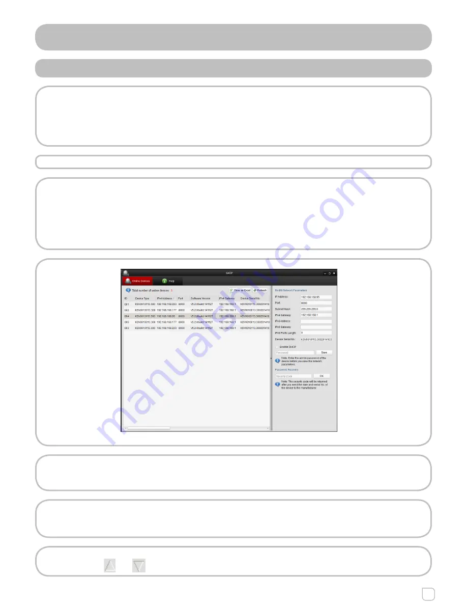
After  launch  the  SADP  software,  it  automatically  searches  the  online  devices
every  15  seconds  from  the  subnet  where  your  computer  locates.  It  displays  the
total  number  and  information  of  the  searched  devices  in  the  Online  Devices
interface.  Device  information  including  the  device  type,  IP  address,  port  number,
gateway,  etc.  will  be  displayed.

Figure  A.1.1 - Search  Online  Devices


Note:

Device  can  be  searched  and  displayed  in  the  list  in  15  seconds  after  it  went
online;  it  will  be  removed  from  the  list  in  45  seconds  after  it  went  offline.

• Search  online  devices  manually

You  can  also  click  Refresh  to  refresh  the  online  device  list  manually.  The  new-
ly

 searched  devices  will  be  added  to  the  list.

Note:

You  can  clic        or         on  each  column  heading  to  order  the  information;  you

Summary of Contents for KSV0010013.300

Page 1: ...Network Camera User Manual...

Page 2: ...readily improve or update the products or procedures described in the manual DISCLAIMER STATEMENT Underwriters Laboratories Inc UL has not tested the performance or reliability of the security or sig...

Page 3: ...received including interference that may cause undesired operation EU CONFORMITY STATEMENT This product and if applicable the supplied accessories too are marked with CE and comply therefore with the...

Page 4: ...l shock do not expose the indoor used product to rain or moisture This installation should be made by a qualified service person and should conform to all the local codes Please install blackouts equi...

Page 5: ...the product cover with fingers directly because the acidic sweat of the fingers may erode the surface coating of the product cover Please use a soft and dry cloth when clean inside and outside surface...

Page 6: ...cal Parameters 25 6 2 Configuring Time Settings 26 6 3 Configuring Network Settings 28 6 3 1 Configuring TCP IP Settings 28 6 3 2 Configuring Port Settings 29 6 3 3 Configuring PPPoE Settings 30 6 3 4...

Page 7: ...tings 61 7 2 Configuring Recording Schedule 62 7 3 Configuring Snapshot Settings 65 Chapter 8 PlayBack 67 Chapter 9 Log Searching 69 Chapter 10 Others 70 10 1 Managing User Account 70 10 2 Configuring...

Page 8: ...rsion Vista Win7 Server 2003 Server 2008 32bits CPU Intel Pentium IV 3 0 GHz or higher RAM 1G or higher Display 1024 768 resolution or higher Web Browser Internet Explorer 6 0 and above version Apple...

Page 9: ...via a LAN you need to connect the network camera in the same subnet with your computer and install the SADP software to search and change the IP of the network camera For the detailed introduction of...

Page 10: ...nge the IP address and subnet mask to the same subnet as that of your computer 3 Enter the IP address of network camera in the address field of the web browser to view the live video Note The default...

Page 11: ...tailed IP address configuration of the camera 3 Save the static IP in the router 4 Set port mapping e g 80 8000 8200 and 554 ports The steps for port mapping vary depending on different routers Please...

Page 12: ...g Note Refer to Appendix 2 for detailed information about port mapping 5 Configure the DDNS settings in the setting interface of the router 6 Visit the camera via the applied domain name Connecting th...

Page 13: ...figuring DDNS Settings for detailed configuration 3 Visit the camera via the applied domain name Private Domain Name Resolution Figure 2 2 5 Private Domain Name Resolution STEPS 1 Install and run the...

Page 14: ...192 168 2 95 and hit the enter key to enter the login interface 3 Input the user name and password and click Login Note The default user name is admin and the password is 12345 Figure 3 1 1 Login Int...

Page 15: ...User Manual Figure 3 1 3 Install Plug in 1 Figure 3 1 4 Install Plug in 2 Note You may have to close the web browser to install the plug in Please reopen the web browser and log in again after the plu...

Page 16: ...reless network is required before you start Wireless Connection in Manage Mode STEPS 1 Enter the Wi Fi configuration interface Configuration Advanced Configuration Network Wi Fi Figure 4 1 1 Wireless...

Page 17: ...o connect the wireless camera via a router The scenario is the same as you connect the camera and the PC directly with a network cable STEPS 1 Choose Ad hoc mode Figure 4 1 3 Wi Fi Setting Ad hoc 2 Cu...

Page 18: ...obably use Open System which is sometimes known as SSID Authentication Key length This sets the length of the key used for the wireless encryption 64 or 128 bit The encryption key length can sometimes...

Page 19: ...APOL version Select the version used 1 or 2 in your access point CA Certificates Upload a CA certificate to present to the access point for authentication EAP PEAP User Name Enter the user name to pre...

Page 20: ...PS PBC Mode PBC refers to the Push Button Configuration in which the user simply has to push a button either an actual or virtual one as the button on the configuration interface of the IE browser on...

Page 21: ...he network usually the Access Point of the network STEPS 1 Choose a wireless connection on the list and the SSID is shown Figure 4 2 2 Wi Fi Settings WPS PIN Mode 2 Choose Use route PIN code If the PI...

Page 22: ...ced Configuration Network TCP IP Or Configuration Basic Configuration Network TCP IP Figure 4 3 1 TCP IP Settings 2 Select the NIC as wlan 3 Customize the IPv4 address the IPv4 Subnet Mask and the Def...

Page 23: ...ick each tab to enter Live View Playback Log and Configuration interface Display Control Click each tab to adjust the layout and the stream type of the live view Live View Window Display the live view...

Page 24: ...the Stream Type to Video Audio referring to Section 6 4 Full screen Mode You can double click on the live video to switch the current live view into full screen or return to normal mode from the full...

Page 25: ...uration Interface 2 Configure the following settings Live View Parameters Set the protocol type and live view performance Protocol Type TCP UDP MULTICAST and HTTP are selectable TCP Ensures complete d...

Page 26: ...he saving paths of the captured pictures and clipped video files Valid for the pictures you captured with the web browser Save snapshots in live view to Set the saving path of the manually captured pi...

Page 27: ...c network you should use a NTP server that has a time synchronization function such as the server at the National Time Center IP Address 210 72 145 44 If the camera is set in a customized network NTP...

Page 28: ...h versions may be configured simultaneously without conflicting to each other and at least one IP version should be configured STEPS 1 Enter TCP IP Settings interface Configuration Basic Configuration...

Page 29: ...POSE You can set the port No of the camera e g HTTP port RTSP port and HTTPS port STEPS 1 Enter the Port Settings interface Configuration Basic Configuration Network Port Or Configuration Advanced Con...

Page 30: ...er Name and Password should be assigned by your ISP 4 Click Save to save and exit the interface Note A reboot is required for the settings to take effect 6 3 4 CONFIGURING DDNS SETTINGS PURPOSE If you...

Page 31: ...icalname of the device hostname 3 Enter the User Name and Password registered on the DDNS Website Note For KseniaDDNS the user name is the hostname without the kseniadns com suffix 4 Click Save to sav...

Page 32: ...the IP Server you have to apply a static IP subnet mask gateway and preferred DNS from the ISP The Server Address should be entered with the static IP address of the computer that runs the IP Server s...

Page 33: ...etting the Trap Address the camera can send the alarm event and exception messages to the surveillance center Note The SNMP version you select should be the same as that of the SNMP software And you a...

Page 34: ...ard is supported by the network cameras and when the feature is enabled the camera data is secured and user authentication is needed when connecting the camera to the network protected by the IEEE 802...

Page 35: ...lay and network congestion by configuring the priority of data sending STEPS 1 Enter the QoS Settings interface Configuration Advanced Configuration Network QoS Figure 6 3 10 QoS Settings 2 Configure...

Page 36: ...e parent directory is selected you have the option to use the Device Name Device Number or Device IP for the name of the directory and when the Child Directory is selected you can use the Camera Name...

Page 37: ...Network UPnP 2 Check the checkbox to enable the UPnP function The name of the device when detected online can be edited Figure 6 3 12 Configure UPnP Settings 6 3 10 EMAIL SENDING TRIGGERED BY ALLARM...

Page 38: ...ckbox to enable SSL if it is required by the SMTP server Attached Image Check the checkbox of Attached Image if you want to send emails with attached alarm images Interval The interval refers to the t...

Page 39: ...NAT 2 Choose the port mapping mode To port mapping with the default port number you can choose Port Mapping Mode as Auto To port mapping with the customized port numbers you can choose Port Mapping Mo...

Page 40: ...ttps E g If you set the port number as 443 and the IP address is 192 168 2 95 you may access the device by inputting https 192 168 2 95 443 via the web browser STEPS 1 Enter the HTTPS settings interfa...

Page 41: ...Create the authorized certificate 1 Click Create Button to create the certificate request 2 Download the certificate request and submit it to the trusted certificate authority for signature 3 After r...

Page 42: ...e bandwidth is limited 3 You can customize the following parameters for the selected main stream or sub stream Video Type Select the stream type to video stream or video audio composite stream The aud...

Page 43: ...erval to 1 400 SVC Scalable Video Coding is an extension of the H 264 AVC standard Set it OFF or ON according to your actual needs 4 Click Save to save the settings 6 4 2 CONFIGURING AUDIO SETTINGS ST...

Page 44: ...assigns more encoding resource to the region of interest to increase the quality of the ROI whereas the background information is less focused STEPS 1 Enter the ROI settings interface Configuration Ad...

Page 45: ...OI encoding and you can also name the ROI area The dynamic region refers to the ROI defined by intelligent analysis such as human face detection You can choose the Image Quality Enhancing level for th...

Page 46: ...Configuration Image Display Settings 2 Set the image parameters of the camera You can configure brightness contrast saturation shade and sharp Figure 6 5 1 Display Settings Descriptions of parameter...

Page 47: ...example if in the surveillance scene there is a fluorescent lamp you can choose the white balance type as the Fluorescent Lamp Figure 6 5 2 White Balance Digital Noise Reduction Close Normal Mode and...

Page 48: ...tings 2 Check the corresponding checkbox to select the display of camera name date or week if required 3 Edit the camera name in the text field of Camera Name 4 Select from the drop down list to set t...

Page 49: ...ideo stream Note Up to 4 text overlays are configurable Figure 6 5 5 Text Overlay Settings 6 5 4 CONFIGURING PRIVACY MASK PURPOSE Privacy mask enables you to cover certain areas on the live video to p...

Page 50: ...he draws 5 Click Save to save the settings 6 5 5 CONFIGURING PICTURE OVERLAY PURPOSE Picture overlay enables you to overlay a picture on the image This function enables a certain enterprise or users t...

Page 51: ...the network camera to respond to alarm events including motion detection video tampering alarm input alarm output and exception These events can trigger the alarm actions such as Notify Surveillance...

Page 52: ...tion 3 Click Draw Area Click and drag the mouse on the live video image to draw a motion detection area Note You can draw up to 8 motion detection areas on the same image 4 Click Stop Drawing to finis...

Page 53: ...set the arming schedule you can copy the schedule to other days 5 Click Save to save the settings Note The time of each period can t be overlapped Up to 8 periods can be configured for each day Figure...

Page 54: ...rm is triggered and upload the picture to a FTP server Note Set the FTP address and the remote FTP server first Refer to Section 6 3 8 for detailed information Trigger Channel The video will be record...

Page 55: ...ng Schedule for Motion Detection in Section 6 6 1 5 Check the checkbox to select the linkage method taken for the video tampering Audible warning notify surveillance center send email and trigger alar...

Page 56: ...ork Camera User Manual Figure 6 6 6 Alarm Input Settings 3 To set the arming schedule and linkage method for the allarm input please refer to Tasks 2 and Tasks 3 in Section 6 6 1 Figure 6 6 7 Linkage...

Page 57: ...or Manual The delay time refers to the time duration that the alarm output remains in effect after alarm occurs 4 Click Edit to enter the Edit Schedule Time interface The time schedule configuration i...

Page 58: ...OTHER ALLARM Some of the camera support PIR passive infrared sensor alarm And you can configure the PIR alarm according to the steps in this chapter STEPS 1 In the Other Alarm configuration interface...

Page 59: ...and you will see two red squares on each end drag one of the red squares to define the arming area Figure 6 6 13 Draw Crossing Line And you can select the directions as A B A B and B A A B Only the ar...

Page 60: ...et the value as 0 alarm is triggered immediate ly after the object entering the region Sensitivity Range 1 100 The value of the sensitivity defines the size of the object which can trigger the alarm w...

Page 61: ...to store the recorded files log files etc STEPS 1 Add the network disk 1 Enter the NAS Network Attached Storage Settings interface Configuration Advanced Configuration Storage NAS Figure 7 1 1 Add Net...

Page 62: ...iew Disk Status Note Up to 8 NAS disks can be connected to the camera To initialize and use the SD card after insert it to the camera please refer to the steps of NAS disk initialization 7 2 CONFIGURI...

Page 63: ...59 55 The Pre record time can be configured as No Pre record 5 s 10 s 15 s 20 s 25 s 30 s or not limited Post record The time you set to stop recording after the scheduled time or the event For examp...

Page 64: ...mal If you select Normal the video will be recorded automatically according to the time of the schedule Record Triggered by Motion Detection If you select Motion Detection the video will be recorded w...

Page 65: ...ngs of this day to the whole week You can also check any of the checkboxes before the date and click Copy 4 Click Ok to save the settings and exit the Edit Record Schedule interface 6 Click Save to sa...

Page 66: ...ckbox Upload event triggered snapshots to FTP STEPS 1 Configure the FTP settings and check Upload Picture checkbox in FTP Settings interface Please refer to Section 6 3 8 Configuring FTP Settings for...

Page 67: ...ored in the network disks or SD cards STEPS 1 Click Playback on the menu bar to enter playback interface Figure 8 1 1 Playback Interface 2 Select the date and click Figure 8 1 2 Search Video 3 Click t...

Page 68: ...ou can choose the file paths locally for downloaded playback video files and pictures in Local Configuration interface Please refer to Section 6 1 for details Drag the progress bar with the mouse to l...

Page 69: ...card in the camera STEPS 1 Click Log Tab on the menu bar to enter log search interface Figure 9 1 1 Log Search Interface 2 Set the log search conditions to specify the search including the Major Type...

Page 70: ...counts Up to 15 user accounts can be created Figure 10 1 1 User Information Add a User STEPS 1 Click Add to add a user 2 Input the new User Name select Level and input Password Note The level indicate...

Page 71: ...4 Click Ok to finish the user modification Figure 10 1 3 Modify a User Delete a User STEPS 1 Select the user you want to delete and click Delete 2 Click Ok when dialogue box pops up to confirm the op...

Page 72: ...US VISIT PURPOSE Enabling this function allows visit for whom doesn t have the user name and password of the device STEPS 1 Enter the Anonymous Visit interface Configuration Advanced Configuration Sec...

Page 73: ...Configuration Advanced Configuration Security IP Address Filter Figure 10 4 1 IP Address Filter Interface 2 Check the checkbox of Enable IP Address Filter 3 Select the type of IP Address Filter in the...

Page 74: ...from filter list and click Modify button 2 Modify the IP address in the text filed Figure 10 4 3 Modify an IP 3 Click the Ok button to finish modification Delete an IP Address Left click an IP addres...

Page 75: ...l No Firmware Version Encoding Version Number of Channels Number of HDDs Number of Alarm Input and Number of Alarm Output are displayed The information cannot be changed in this menu It is the referen...

Page 76: ...stem Maintenance Or Configuration Advanced Configuration System Maintenance 1 Click Export to save the configuration file of the current device 2 Click Browse to select the saved configuration file an...

Page 77: ...be the same as the serial port parameters of the camera Transparent Channel Connect a serial device directly to the camera The serial device will be controlled remotely by the computer through the net...

Page 78: ...y the tel net and uncheck the checkbox to disable the telnet 3 Check the checkbox of Enable SSH to enable the data communication secu rity and uncheck the checkbox to disable the SSH 10 9 SERVICE SETT...

Page 79: ...earches the online devices every 15 seconds from the subnet where your computer locates It displays the total number and information of the searched devices in the Online Devices interface Device info...

Page 80: ...network parameters e g IP address and port number 3 Enter the password of the admin account of the device in the Pass word field and click to save the changes Figure A 1 2 Modify Network Parameters R...

Page 81: ...1G The settings vary depending on different models of routers STEPS 1 Select the WAN Connection Type as shown below Figure A 2 1 Select the WAN Connection Type 2 Set the LAN parameters of the router a...

Page 82: ...ports of another camera as 81 8001 555 8201 with IP 192 168 1 24 Refer to the steps as below STEPS 1 As the settings mentioned above map the port 80 8000 554 and 8200 for the network camera at 192 16...

Reviews: