4 Valve Description
18 of 72
0570.81/22-EN
4.4 Gate valves to DIN/EN in pressure seal design
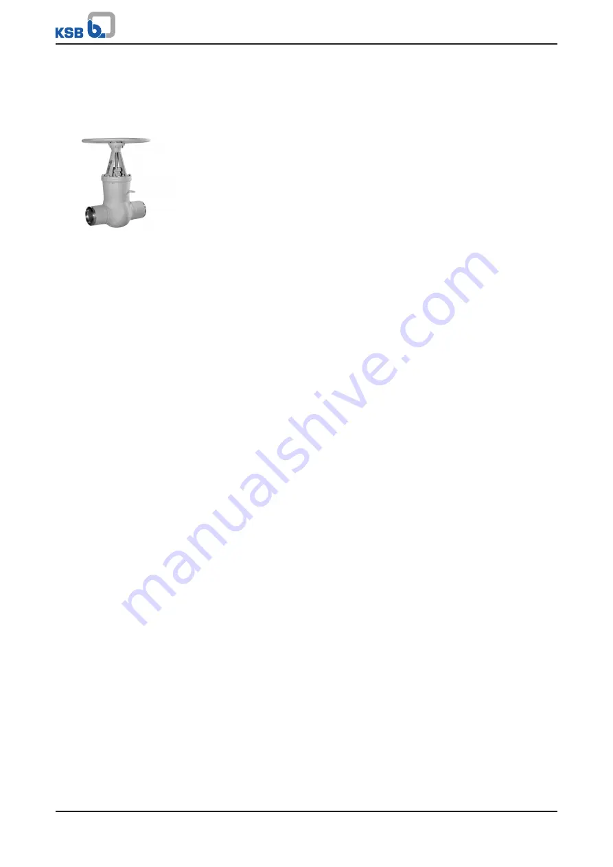
4.4.1 AKG-A/AKGS-A
Fig. 6:
AKG-A/AKGS-A
4.4.1.1 General description
▪
Gate valve with pressure seal bonnet
Valve for preventing backflow in industrial plants, power stations, process
engineering and shipbuilding.
4.4.1.2 Design details
Design
▪
Pressure seal design
▪
Non-rotating stem
▪
Split wedge
▪
Yoke head suitable for mounting electric and pneumatic actuators (DIN ISO 5210)
Variants
▪
Body made of forged steel
▪
Position indicator
▪
Limit switch(es)
▪
Drain branch
▪
Hard-faced back seat
▪
Disc spring supported yoke head
▪
Parallel discs
▪
Bypass
▪
Spur gear
▪
Bevel gear
▪
Electric actuators
▪
Pneumatic actuators
▪
Actuating bush for remote actuation
▪
Other flange designs
▪
Other butt weld end versions
▪
Inspections to technical codes such as TRD/TRB/AD2000 – German Steam Boiler /
Pressure Vessel Regulations – or to customer specification
4.4.1.3 Function
Design
Gate valves with wedge discs 360 comprise body 100 with welded stellited seat rings
515, wedge discs 360 with stellited seating faces, bonnet 139 with gland packing 461
and yoke 166 with the actuating element.
Sealing
Shut-off is performed by two wedge discs 360 pressed against seat rings 515; they are
flexibly mounted in wedge/disc holder 367 and supported by replaceable thrust
inserts 553 via pins 563.
Wedge/disc holder 367 is screwed onto stem 200. A retainer prevents wedge discs 360
from twisting in wedge/disc holder 367. To prevent twisting of the obturator
components, the wedge/disc holder is guided in the body by lateral guide ribs 752.
The valve is equipped with a pressure seal bonnet.
The pressure inside body 100 presses bonnet 139 against joint ring 411.1, which is
supported by compression ring 501. Studs 902.2 and hexagon nuts 920.6, which are
supported by thrust plate 414, ensure that bonnet 139 is held in position against joint
ring 411.1, even if there is no pressure inside body 100.


