background image

Omega

1384.8/4--10

Operating instructions

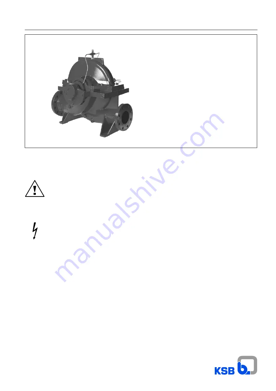
Volute casing pump

with radial impeller

Pump set

Horizontal installation -- 3 E

These operating instructions contain fundamental information and precautionary notes.

Please read the manual thoroughly prior to installation of unit, electrical connection and

commissioning. It is imperative to comply with all other operating instructions referring to

components of individual units.

Any work on the unit must only be carried out with the electrical connections (incl. control cable)

disconnected (or unplugged). Make sure that the pump set cannot be switched on accidentally.

Ident--No.:

01 059 616

Summary of Contents for Omega Series

Page 1: ...read the manual thoroughly prior to installation of unit electrical connection and commissioning It is imperative to comply with all other operating instructions referring to components of individual units Any work on the unit must only be carried out with the electrical connections incl control cable disconnected or unplugged Make sure that the pump set cannot be switched on accidentally Ident No...

Page 2: ...Omega 2 For usage in hazardous locations refer to supplementary operating instructions 1387 81 ...

Page 3: ...eights 7 5 Installation at Site 7 5 1 Safety Regulations 7 5 2 Checks to Be Carried out Prior to Installation 7 5 3 Installing the Pump Unit 8 5 4 Connecting the Piping 8 5 5 Final Check 8 6 Commissioning Start up Shutdown 9 6 1 Commissioning 9 6 2 Shaft Seal 9 6 3 Venting 9 6 4 Commissioning 9 6 5 Shutdown Storage Preservation 10 6 6 Returning to Service after Storage 10 7 Maintenance Repair 10 7...

Page 4: ...lined under specific headings 2 1 Marking of Instructions in the Manual The safety instructions contained in this manual whose non observance might cause hazards to persons are specially mar ked with the general hazard sign namely safety sign in accordance with DIN 4844 W9 The electrical danger warning sign is safety sign in accordance with DIN 4844 W8 The word Caution is used to introduce safety ...

Page 5: ...n and Manufacture of Spare Parts Modifications or alterations of the machine are only permitted after consultation with the manufacturer Original spare parts and accessories authorized by themanufacturerensuresafety The use of other parts can invalidate any liability of the manu facturer for consequential damage 2 8 Unauthorized Modes of Operation The warranty relating to the operating reliability...

Page 6: ...ent 3 2 Interim Storage Preservation When the unit is temporarily put into storage only the wetted low alloy components e g JL1040 GG 25 must be preser ved Commercially available preservatives can be used for this purpose Please observe the manufacturer s instructions for application removal 4 Description of the Product and Accesories 4 1 Technical Specification Design The KSB pump of the Omega se...

Page 7: ...me x 1 Coupling and coupling guard x 1 Sealing and flushing water pi ping x x Set of pressure gauges x x Cyclone separator with pipework x x Vent valve manual or automatic x x Temperature sensor for rolling element bearings PT 100 x x Signal transmitter for PT 100 x x Drain line x x 2 included in standard scope of supply 4 6 Dimensions and Weights For dimensions and weights please refer to the tab...

Page 8: ...ons see appendix 5 4 Connecting the Piping Never use the pump itself as an anchorage point for the piping Suction lift lines shall be laid with a rising slope towards the pump and suction head lines with a downward slope towards the pump The pipelines shall be anchored in close proximity to the pump and connected without transmitting any stresses or strains Their weight must not exert any load on ...

Page 9: ...tion the pump cannot re ach its duty point vibrations and overheating will be the conse quence The unit or the shaft seal might be damaged Correct direction of rotation The direction of rotation must correspond to the direction indi cated by the arrow on the pump This can be verified by swit ching the pump on and then off again immediately Before checking the direction of rotation make sure that t...

Page 10: ...dy for instant start up and to prevent the formation of deposits within the pump and the pump intake area start up the pump set regularly once a month or once every 3 month for a short time approx 5 minutes during prolonged shutdown periods Priorto an ope ration check run ensure that there is sufficient liquid available for operating the pump 2 The pump is removed from the pipe and stored Before p...

Page 11: ...n the mo tor shall be governed by the specifications and regulations of the respective motor supplier Dismantling and reassembly must always be carried out in ac cordance with the relevant general drawing The general dra wing and other relevant documents are found in the annex The dismantling sequence can be derived from the general dra wing In case of damage you can always contact our nearest cus...

Page 12: ...h fine pitch MA in Nm M4 3 1 4 4 1 0 2 15 M5 6 1 8 7 2 00 4 25 M6 10 4 14 9 3 40 7 30 M8 25 2 36 1 8 30 17 7 M8x1 27 2 39 0 8 90 19 1 M10 49 5 71 0 16 2 34 8 M10x1 25 52 5 75 4 17 3 36 9 M12 85 2 122 2 28 0 59 9 M12x1 5 89 5 128 5 29 4 62 9 M12x1 25 93 9 134 7 30 8 66 0 M16 211 302 7 69 2 148 M16x1 5 226 324 7 74 3 159 M20 412 591 9 135 290 M20x1 5 461 661 0 151 324 M24 710 1019 6 233 276 500 M24x...

Page 13: ...ecured by the disc 550 01 and the circlip 932 To fit the shaft protecting sleeve 524 01 shaft seal housing 441 V ring 411 01 and bearing cover 360 at the non drive end proceed as described above for the drive side Heat the deep groove ball bearing 321 and fit it onto the sleeve 520 Pushthesleeve 520 withdeep grooveballbearing 321 onto the pump shaft 211 with key 940 01 inserted Tension the rotor p...

Page 14: ...y a new impeller can be supplied at short notice Clearance as new Dimensions of impeller wear ring No Pump size Shaft unit Nominal clea rance max perm D2 D1 Min clearance S min Max clearance S max D W 2 D 5 b mm mm mm mm mm 1 80 210 0 3 0 15 0 2 134 r6 18 2 80 270 0 3 0 15 0 2 134 r6 18 3 80 370 40 0 3 0 15 0 2 134 r6 18 4 100 250 40 0 35 0 17 0 2 163 r6 22 5 100 310 0 35 0 17 0 2 163 r6 22 6 100 ...

Page 15: ...Thermometer suction discharge nozzle if applicable Check temperature weekly Flushing line sight glass if applicable Check flushing water flow weekly Water flows Vibration measurement if applicable Check weekly Bearing temperature if applicable Check weekly Section 7 2 Coupling Check weekly Annex from p 47 detailed manufacturer information Drive if applicable See manufacturer s documentation Ensure...

Page 16: ...boxinsertandgland cover and tighten them so that the packing rings adapt to the gland space Then loosen the gland cover again to relieve the loadonthepacking Thisprocedureis notnecessary ifmoulded packing rings are used Commissioning Whenthepump isstarted up the glandmustonlybe gentlytigh tened by hand A high leakage rate approx 50 to 200 drops perminute dependingontheliquidbeingpumped mustbeac ce...

Page 17: ... 60 10 125 500 50 60 M 7 N 4 60 HJ 92 N 60 11 150 290 12 150 360 13 150 460 14 150 605 60 70 M 7 N 4 70 HJ 92 N 70 15 200 320 60 70 M 7 N 4 70 HJ 92 N 70 16 200 420 17 200 520 18 200 670 70 80 M 7 N 4 80 HJ 92 N 80 19 250 370 70 80 M 7 N 4 80 HJ 92 N 80 20 250 480 80 90 M 7 N 4 90 HJ 92 N 90 21 250 600 80 90 M 7 N 4 90 HJ 92 N 90 22 300 300 70 80 M 7 N 4 80 HJ 92 N 80 23 300 435 80 90 M 7 N 4 90 H...

Page 18: ...ing 1 at the inner diameter The O ring 2 can be slightly lubricated to facilitate assembly The complete rotating assembly is pushed onto the shaft pro tection sleeve in compliance with the installation dimensions which are given in the mech seal drawing or until it reaches the stop on the shaft protection sleeve Finally the grub screws are tightened and secured with LOCTITE Item Description Materi...

Page 19: ...f the leakage amount Changes in opera ting conditions must be documented If an excessive tempera ture rise is detected the mechanical seal must be shut down for safety reasons During the warranty period the mechanical seal shallonly bere moved and dismantled with the manufacturer s approval or un der instructions of the mechanical seal manufacturer s service engineers If the fault cannot be remedi...

Page 20: ...icles The seat ring 8 together with the relevant O ring 9 is fitted into the seal cover see general drawing The O ring can be lubricated for easy sliding movement Special attention must be given to ensure that pressure is applied evenly The contact surfaces are generally fitted dry In mechanical seals ofthe M74 Ndesign the rotating assembly is supplied as one unit consisting of a housing and pin 1...

Page 21: ...he mechanical seal can be expected to give trouble free opera tion Should the mechanical seal fail the liquid to be sealed off may spurt out Take suitable precautions to pre vent hazards to persons and the environment e g install splash guards wear safety goggles etc Proper disposal of leakage shall be arranged for and supervised by the operator Faults Determine and document the nature of the faul...

Page 22: ... work on the mechanical seal is only permitted with the pump shut down and pump pressure released Removal of the mechanical seal shall be performed analo gously with mechanical seal installation but in reverse order Removing the subassembly See section 7 3 Grub screw 7 und Dichtringe 2 9 nach jederDemontage erneuern Spare parts Only genuine spare parts shall be used Non compliance with this requir...

Page 23: ...health and safety regulations must be adhe red to Unauthorized modifications and alterations liable to jeopardize the safe operation of the mechanical seal are not permitted J DECLARATION within the meaning of EC Directive Machinery 98 37 EC A mechanical seal does not function independently It is inten ded to be incorporated into or assembled with machinery J OPERATING LIMITS Shaft diameter dw 18 ...

Page 24: ...otified immediately of any damaged goods or missing parts The instructions given below shall apply both to mechanical seals delivered and stored in their undamaged original packa ging and to mechanical seals already installed in a pump which have not been in operation yet The mechanical seals need not be preserved D Do not apply anti corrosives Risk of deposits and possible chemical attacks on ela...

Page 25: ...equence D Slide the degreased O ring onto the seat ring D Cover the contact face of the seat ring with a cardboard washer Generously lubricate the seat ring with water or al cohol and press it slowly and evenly into its seat Use a spa cer if necessary Check squareness of seat ring to the shaft axis D Apply a thin coat of grease to the shaft protecting sleeve in the mechanical seal area Never use m...

Page 26: ...lfunction involving hazards to persons and the environment D forfeiture of any and all warranty claims To ensure quick mechanical seal replacement we recommend to stock a complete spare seal J REMOVING THE SEAL FROM THE PUMP D Shut down the pump allow to cool down and release pres sure as per operating instructions D No product should contact the mechanical seal Drain the pump if necessary D Secur...

Page 27: ...ft unit dw 90 mm General instructions concerning assembly installation com missioning maintenance faults and repair have already been given in sections 8 2 1 and 8 2 2 See Operating manual from Type BURGMANN S operating manual for seal type H75N ...

Page 28: ...l occupational health and safety regulations must be adhe red to Unauthorized modifications and alterations liable to jeopardize the safe operation of the mechanical seal are not permitted J DECLARATION within the meaning of EC Directive Machinery 98 37 EC A mechanical seal does not function independently It is inten ded to be incorporated into or assembled with machinery J OPERATING LIMITS Shaft ...

Page 29: ...preservatives chosen with the materials of construction and the elastomer components of the mechanical seal D Verify that mechanical seal movementis notrestricted byre sin deposits or sticking During storage seal face materials and elastomers will un dergo material specific time dependent changes distortion ageing which can impair the perfect function of themechanical seal The specified storage pe...

Page 30: ...ontact face of the seat ring with a cardboard washer Generously lubricate the seat ring with water or al cohol and press it slowly and evenly into its seat Use a spa cer if necessary Check squareness of seat ring to the shaft axis D Apply a thin coat of grease to the shaft protecting sleeve in the mechanical seal area Never use mineral oil base lubricants on sealing ele ments made of ethylene prop...

Page 31: ...unction involving hazards to persons and the environment D forfeiture of any and all warranty claims To ensure quick mechanical seal replacement we recommend to stock a complete spare seal J REMOVING THE SEAL FROM THE PUMP D Shut down the pump allow to cool down and release pres sure as per operating instructions D No product should contact the mechanical seal Þ Drain the pump if necessary D Secur...

Page 32: ...ller wear ring 4 4 4 6 6 8 50 211 940 920 932 Shaft with keys and shaft nuts 1 1 2 2 2 3 30 321 Rolling element bearing 2 2 4 4 6 8 100 524 Shaft protecting sleeve 4 4 4 6 6 8 50 461 Packing ring 32 32 48 48 48 64 40 411 412 421 Set of sealing ele ments 4 6 8 8 9 12 150 433 Mechanical seal Spring loaded ring 4 6 8 8 8 12 90 Seat ring 4 6 8 8 8 12 90 O rings 4 6 12 16 16 20 150 Seals on 4 6 12 16 1...

Page 33: ... Pump shaft diameter 40 50 60 70 80 90 80 210 80 270 80 370 100 250 100 310 100 375 125 230 125 290 125 365 125 500 150 290 150 360 150 460 150 605 200 320 200 420 200 520 200 670 250 370 250 480 250 600 300 300 300 435 300 560 300 700 350 360 350 430 350 450 ...

Page 34: ... 19 14 254 254 0 35 0 35 1000 700 0 048 0 058 16 25 28 37 5 100 310 15 11 325 325 0 35 0 35 1000 700 0 092 0 110 16 25 28 37 5 100 375 13 10 408 408 0 35 0 35 1000 700 0 229 0 275 16 25 28 37 5 125 230 23 17 245 245 0 35 0 35 1500 1000 0 161 0 193 16 25 28 37 5 125 290 19 12 301 301 0 35 0 35 1500 1000 0 125 0 150 16 25 28 37 5 125 365 14 10 392 392 0 35 0 35 2000 1500 0 261 0 313 16 25 28 37 5 12...

Page 35: ...6 346 8 250 24 25 28 37 5 350 360 39 27 373 373 0 5 0 5 5000 3000 1 116 1 563 10 25 15 37 5 350 430 57 40 430 430 0 6 0 6 5000 3000 2 232 3 125 10 25 15 37 5 350 510 52 36 35 518 518 518 0 6 0 6 0 6 5000 3000 3 393 4 750 10 25 15 37 5 1 Casing material JL 1040 and GGG NiCrNb 20 2 2 Casing material JS 1030 and 1 4517 3 Casing material JS 1030 1 4 times the given value 4 Casing material 1 4517 1 9 t...

Page 36: ...piping F F F F F Suction head too high NPSHavailable too low water level too low Check mode of operation Correct suction conditions Increase positive suction head Increase back pressure by throttling Install pump at a lower level Alter intake pipe if resistances are too high F F F F Air is drawn in at shaft seal Clean sealing liquid line possibly introduce sealing liquid from an external source or...

Page 37: ...mpeller if necessary 1 F F F F F Speed too high Reduce speed In the case of persistent overloading turn down impeller if necessary 1 F Tie bolts seals Check Tighten tie bolts Replace gaskets Check pipe connections and pump moun ting if necessary improve mounting of pi ping F Worn shaft seal Check flushing sealing liquid pressure clean sealing liquid line possibly introduce sealing liquid from an e...

Page 38: ...urce or increase its pressure Increase cooling liquid flow Clean cooling liquid line F F Pump mis aligned or reso nance vibrations in the pi ping Re align pump drive Check piping connections and pump mounting if necessary improve mounting of piping Apply vibration damping measures F Excessive axial thrust Check duty point pump selection Check mode of operation Check suction side flow F Too little ...

Page 39: ...in liquid Vent Check integrity of suction pipe seal if necessary F F F F F Air drawn in at pump in let Correct suction conditions Reduce flow velocity at suction pipe en try Increase suction head Check integrity of suction pipe and seal if necessary Replace defective pipes F Cavitation rattling noise Correct suction conditions Check mode of operation Increase suction head Install pump at a lower l...

Page 40: ... 1 4 1 4 Check torsional play of coupling see section Coupling If available switch to stand by pump or carry out a test run for 5 min every 20 000 operating hours 2 3 Replace deep groove ball bearings see section 7 3 Dismantling and 7 4 Reassembly every 4 years or if total head of pump drops 2 6 General inspection and overhaul of pump in accordance with the operating instructions Check and renew i...

Page 41: ...PEX 47 Correlation between tightening torques dimension P and clearance S1 49 Trouble shooting 50 General drawing of pump with parts list Shaft seal Gland packing 52 General drawing of pump with parts list Shaft seal Mechanical seal 54 Mechanical seals standard design 56 Shaft seal mechanical seals Type Crane 58U and 58B 58 Dimension table Omega 80 210 up to 150 605 60 Dimension tables Omega 200 3...

Page 42: ...nd Direction of rotation anticlockwise viewed from the drive end Direction of rotation clockwise viewed from the drive end Type of installation DJ 2 Version with intermediate bearing Pump set with close coupled motor type IM B3 1 Baseplate baseframe coupling guard and motor height adjustment Type of installation 3E Omega 42 Types of installation 1 General arrangement drawing Pump set 3 E Baseplate...

Page 43: ...4 840 89 4 03 900 01 681 550 54 89 4 54 1 550 55 909 54 890 Shims Adjusting screw 1 for screw set without adjusting screw 909 54 Type of Installation 3E Motor Height Adjustment Baseplate with adjusting screw and pedestal 901 06 550 56 890 891 550 10 920 10 900 01 901 05 89 4 03 901 54 550 54 550 55 909 54 901 57 550 57 180 54 840 681 Adjusting screw Pedestal ...

Page 44: ...56 550 10 920 10 900 01 901 05 89 4 03 901 54 902 54 920 54 550 54 89 4 54 592 54 891 2 1 1 optional depending on height required 2 for long lengths instead of hex head bolts Shim Part no Description 89 4 Shim 180 Pedestal 550 Washer 592 Base 890 Baseplate 900 Screw 901 Hex head bolt 902 Stud 909 Adjusting screw 920 Nut ...

Page 45: ...re and highly pressure resistant Another favourable property of PTFE polytetrafluorethylene is the extremely low friction coefficient which prevents pipe clogging Normally we supply this assembly ready mounted to the pump If this is not the case mount the hoses and fittings as per the attached drawings see appendix Arrangement of sealing water and flush pipes ...

Page 46: ...ption 719 01 Flexible tube 731 02 Nipple joint 731 03 Cross 731 04 Nipple joint 731 05 Pipe bend 731 12 Socket 903 01 Screwed plug Sealing water pipe for mechanical seal 731 02 719 01 731 04 731 03 903 01 Part no Description 719 01 Flexible tube 731 02 Nipple joint 731 03 Cross 731 04 Nipple joint 903 01 Screwed plug ...

Page 47: ...itch off the driver when changes in coupling behaviour occur such as changed running noises D The coupling must be suitably protected against accidental contact Installation Design of types A ADS The N EUPEX coupling types A ADS consist of a coupling part 1 which houses the flexible coupling blocks 12 the finger part 3 and the coupling part 2 which bolts onto part 3 Theboltedconnectionbetweenpart2...

Page 48: ...tween parts 2 and 3 shall be checked for tightening torques and clearance S1 please refer to point 6 6 Aligning the coupling Also refer to section 5 3 2 The couplings will only tolerate misalignment of the shaft ends to be coupled to a certain extent When aligning the coupling the radial and angular misalign ment of the shaft ends should therefore be minimized With identical operating conditions t...

Page 49: ...ommissioning the coupling Measures to be taken prior to commissioning Before commissioning the coupling check the proper installa tion of the flexible coupling elements i e make sure the flexi bles are flush with the hub face and check whether the set screws are properly tightened Also verify coupling alignment and clearance S1 and correct if necessary Check whether all screwed connections have be...

Page 50: ...ect the coupling parts and replace any damaged components Coupling blocks shall always be replaced by complete sets of new coupling blocks only use coupling blocks with identical markings Verify alignment and correct if necessary Check the tightening torques of the screwed connec tion between parts 2 and 3 Maintenance and repair General The torsional play between the two coupling parts shall be ch...

Page 51: ...ear parts Use only genuine N EUPEX flexible blocks as spare parts to ensure correcttorque transmission and trouble free operation Please note On types A and ADS the flexibles can be replaced withoutaxial displacement of the coupled machines After the screwed connection between parts 2 and 3 has been undone part 3 can be shifted in axial direction By rotating part 3 the flexible coupling blocks are...

Page 52: ...2 General drawing of pump with parts list Shaft seal Gland packing Sealed with Loctite 574 ALTEMP Q NB 50 grease Shaft diameter Axial overhang of shaft protec ting sleeve dW A 0 5 40 2 50 2 60 2 70 5 80 4 90 4 ...

Page 53: ... box insert 901 Hex head bolt 211 Pump shaft 458 Neck ring 902 Stud 234 Impeller 461 Lantern ring 903 Screwed plug 321 Deep groove ball bearing 502 Casing wear ring 904 Grub screw 350 Bearing housing 503 Impeller wear ring 920 Nut 360 Bearing cover 520 Sleeve 932 Circlip 411 V ring 524 Shaft protecting sleeve 940 Key 412 O ring 550 Washer 950 Cup spring 421 Radial shaft seal ring 441 Housing for s...

Page 54: ... General drawing of pump with parts list Shaft seal Mechanical seal Sealed with Loctite 574 ALTEMP Q NB 50 grease Shaft diameter Axial overhang of shaft protec ting sleeve dW A 0 5 40 2 50 2 60 2 70 5 80 4 90 4 ...

Page 55: ... 903 Screwed plug 105 02 Upper casing half 441 Housing for shaft seal 920 Nut 211 Pump shaft 457 02 Stuffing box insert 932 Circlip 234 Impeller 503 Impeller wear ring 940 Key 321 Deep groove ball bearing 520 Sleeve 950 Cup spring 350 Bearing housing 524 01 Shaft protecting sleeve 360 Bearing cover 525 02 Spacer sleeve 411 V ring 550 Washer 412 O ring 561 Grooved pin 580 Cap ...

Page 56: ...nnection Standardized mechanical seal to DIN 24960 short design non balanced Sizes for shaft diameter dw 90 mm with multiple spring arrangement Æ 110 211 525 02 411 457 02 524 01 433 901 16 471 d w 90 Flushing line connection Part no Description Part no Description 211 Pump shaft 471 Seal cover 433 Mechanical seal 524 01 Shaft protecting sleeve 441 Housing for shaft seal 525 02 Spacer sleeve 457 0...

Page 57: ...nection Balanced mechanical seal for operating pressures p 16 bar to DIN 24960 Sizes for shaft diameter dw 90 mm with multiple spring arrangement Æ 110 dw 90 211 525 02 411 457 02 524 01 433 901 16 471 Flushing line connection Part no Description Part no Description 211 Pump shaft 471 Seal cover 433 Mechanical seal 524 01 Shaft protecting sleeve 441 Housing for shaft seal 525 02 Spacer sleeve 457 ...

Page 58: ...imensions 780 Retainer 578 Balanced face 305 Grub screw 096 Snap ring 582 092 Spring 500 Seat type BP 583 Thust ring 501 Seat ring 123 O ring 902 Seat type BO 574 Rotating face 123 R O ring 564 Support ring Installation and operation 1 Clean and lightly lubricate the shaft sleeve with a suitable lubricant Caution SealingelementsmanufacturedinEP Elastomermaterials must not come in contact with mine...

Page 59: ...2 092 Assembly is carried out in reverse sequence The following must be noted during assembly The drive cams in the retainer 780 must engage into the groo ves of the thrust ring 583 or the rotating face 574 578 Fit the snap ring 096 into the groove of the retainer 780 lea ving one end of the snap ring protruding by approx 6 12 mm to the side of the drilled hole At the outer circumference of the re...

Page 60: ...310 150 100 37 32 330 330 19 415 355 170 225 300 715 450 100 375 150 100 37 32 370 370 19 415 355 170 260 300 715 520 125 230 210 420 125 290 200 125 41 35 370 370 19 515 400 200 230 366 881 460 125 365 200 125 41 35 370 370 19 515 400 200 260 366 881 520 125 500 450 450 305 610 150 290 400 400 515 245 366 881 490 150 360 200 150 41 37 400 400 19 515 400 200 265 366 881 530 150 460 200 150 41 37 4...

Page 61: ...25 Table 25 11 Class 250 125 500 150 290 150 360 PN 16 Table 16 11 150 460 Class 250 PN 25 Table 25 11 Class 250 150 605 PN 25 Table 25 11 1 Other flange connections on request Flange dimensions Hole pattern All dimensions in mm Standard DN 80 DN 100 DN 125 DN 150 DN 200 d2 k n d2 k n d2 k n d2 k n d2 k n ISO 7005 2 DIN 2501 PN 16 19 160 8 19 180 8 19 210 8 23 240 8 23 295 12 ISO 7005 2 DIN 2501 P...

Page 62: ...15 515 1245 830 300 300 350 36 54 1 33 550 500 655 630 300 360 464 1119 720 300 435 300 38 57 1 51 1 650 550 24 5 730 670 350 365 515 1245 730 300 560 400 300 57 51 700 650 24 5 810 710 350 430 585 1395 860 300 700 400 57 51 750 650 810 750 400 480 585 1395 960 350 360 400 38 57 1 650 550 730 670 350 410 515 1245 820 350 430 450 350 41 60 1 36 54 1 750 650 24 5 810 750 400 465 585 1395 930 350 510...

Page 63: ...0 350 430 PN 10 Table 10 11 Class 125 PN 25 Table 25 11 Class 250 350 510 1 Other flange connections on request Flange dimensions Hole pattern All dimensions in mm Standard DN 200 DN 250 DN 300 DN 350 DN 400 DN 450 d2 k n d2 k n d2 k n d2 k n d2 k n d2 k n ISO 7005 2 DIN 2501 PN 10 23 295 8 23 350 12 23 400 12 23 460 16 28 515 16 28 565 20 ISO 7005 2 DIN 2501 PN 16 23 295 12 28 355 12 28 410 12 28...

Page 64: ...0 270 up to 280 M 125 80 36 29 300 300 415 295 660 435 70 300 380 195 15 80 270 up 315 S 125 80 36 29 300 300 415 320 660 460 85 300 380 195 15 80 370 330 330 295 435 70 450 205 20 100 250 up to 280 M 305 475 70 390 210 20 100 250 up 315 S 330 330 330 500 85 390 210 20 100 310 up to 280 M 150 100 37 32 330 330 415 305 760 475 70 300 450 225 25 100 310 up 315 S 150 100 37 32 415 330 760 500 85 300 ...

Page 65: ... sizes 100 250 up to 100 375 150 100 ISO 7005 2 DIN 2501 BS 4504 PN 16 Table 16 11 23 M20 240 8 19 M16 180 ISO 7005 2 DIN 2501 BS 4504 PN 25 Table 25 11 28 M24 250 8 23 M20 190 8 ANSI B 16 1 Class 250 23 M20 270 12 23 M20 200 Baseplate motor combinations Pump Motor Size Pump Size 100L 112M 132S 132M 160M 160L 180M 180L 200L 225S 225M 250M 280S 280M 315S 315M 315L 315 No of poles 4 4 4 4 2 4 2 4 2 ...

Page 66: ...0 M 320 520 420 250 35 125 230 up 315 S 345 545 420 250 35 125 290 up to 280 M 370 370 320 520 460 275 40 125 290 up 315 S 200 125 41 35 370 370 345 825 545 460 275 40 125 365 200 125 41 35 515 320 825 520 120 366 520 300 45 125 500 up to 280 M 450 450 515 320 520 120 366 610 335 55 125 500 up 315 S 450 450 345 545 610 335 55 150 290 200 150 41 37 400 400 320 1050 520 490 347 50 150 360 200 150 41...

Page 67: ... M24 330 23 M20 235 Pump sizes 150 290 up to 150 360 200 150 ISO 7005 2 DIN 2501 BS 4504 PN 16 Table 16 11 23 M20 295 23 240 8 ISO 7005 2 DIN 2501 BS 4504 PN 25 Table 25 11 28 M24 310 12 28 250 8 ANSI B 16 1 Class 250 28 M24 330 23 270 12 Baseplate motor combinations Pump Motor Size Pump Size 132S 132M 160M 160L 180M 180L 200L 225S 225M 250M 280S 280M 315S 315M 315L 315 No of po les 4 4 4 4 4 4 2 ...

Page 68: ...6 i l2 z 2 Pump Water dependet max fill up to 250 M 320 520 150 460 280 S up to 315 L 200 150 41 37 450 450 380 1050 580 399 610 436 75 150 605 600 500 380 680 740 646 90 150 605 600 500 380 680 740 646 90 200 320 up to 250 M 450 450 590 620 215 570 450 80 200 320 280 S M 450 450 590 440 680 215 570 450 80 up to 250 M 380 620 399 200 420 280 S up to 315 L 250 200 48 41 500 500 440 1240 680 620 517...

Page 69: ...izes 200 320 up to 200 670 250 200 ISO 7005 2 DIN 2501 BS 4504 PN 16 Table 16 11 28 M24 355 23 M20 295 12 ISO 7005 2 DIN 2501 BS 4504 PN 25 Table 25 11 31 M27 370 12 28 M24 310 12 ANSI B 16 1 Class 250 28 M24 387 28 M24 330 Pump sizes 250 370 300 250 ISO 7005 2 DIN 2501 BS 4504 PN 10 Table 10 11 23 M20 400 12 23 M20 350 ISO 7005 2 DIN 2501 BS 4504 PN 16 Table 16 11 28 M24 410 12 28 M24 355 12 ISO ...

Page 70: ...nge dimensions Pump dimensions Weight kg Size DN1 DN2 s1 s2 a1 a2 f h4 h5 h6 i l2 z 2 Pump Water max fill 250 480 300 250 51 48 550 500 1275 800 710 830 145 250 600 300 250 51 48 550 730 480 1275 830 210 515 830 1215 180 300 435 400 300 38 57 1 33 51 1 650 550 730 520 1430 870 210 515 730 905 190 350 360 400 350 38 57 1 36 54 1 520 1415 870 820 865 160 1 for casing material GGG NiCrNb 202 JS 1030 ...

Page 71: ...able 10 11 28 M24 515 23 M20 400 12 ISO 7005 2 DIN 2501 BS 4504 PN 16 Table 16 11 31 M27 525 16 28 M24 410 12 ISO 7005 2 DIN 2501 BS 4504 PN 25 Table 25 11 37 M33 550 31 M27 430 16 ANSI B 16 1 Class 125 28 M24 540 28 M24 432 12 ANSI B 16 1 Class 250 34 572 20 31 M27 451 16 Pump size 350 360 400 350 ISO 7005 2 DIN 2501 BS 4504 PN 10 Table 10 11 28 M24 515 16 23 M20 460 ISO 7005 2 DIN 2501 BS 4504 P...

Page 72: ...p Flange dimensions Pump dimensions Weight kg Size DN1 DN2 s1 s2 a1 a2 f h4 h5 h6 i l2 z 2 Pump Water max fill 300 560 400 300 57 51 700 560 1430 910 860 1425 225 300 700 400 300 57 51 750 650 810 1430 210 585 960 1690 275 350 430 450 350 41 60 1 36 54 1 750 650 810 550 1415 950 210 585 930 1285 240 350 510 400 350 38 57 1 36 54 1 700 1415 840 1395 290 1 for casing material GGG NiCrNb 202 JS 1030 ...

Page 73: ... 7005 2 DIN 2501 BS 4504 PN 10 Table 10 11 28 M24 565 23 M20 460 ISO 7005 2 DIN 2501 BS 4504 PN 16 Table 16 11 31 M27 585 20 28 M24 470 16 ISO 7005 2 DIN 2501 BS 4504 PN 25 Table 25 11 37 M33 600 34 M30 490 ANSI B 16 1 Class 125 31 M27 578 16 28 M24 476 12 ANSI B 16 1 Class 250 34 629 24 31 M27 514 20 Pump size 350 510 400 350 ISO 7005 2 DIN 2501 BS 4504 PN 10 Table 10 11 28 M24 515 23 M20 460 ISO...

Page 74: ...e connection suction side G 1 2 Enter order specific data 1 M 2 Pressure gauge connection discharge side G 1 2 Enter order specific data 4 M 1 if applicable Temperature measuring point bearing Drive end G 3 8 See section 7 2 4 M 2 if applicable Temperature measuring point non drive end G 3 8 See section 7 2 26 M 1 if applicable Thread for SPM measurement drive end M 8 Enter order specific data 26 ...

Page 75: ... 92 D 06008 Halle Saale D 06110 Halle Saale Ersatzteilabteilung Fax 49 345 48 26 4691 Tel 49 345 48 26 0 From In order to ensure the smooth processing of your spare parts inquiry we request that you let us have the following data D The works No is given on the name plate of your pump e g 2 M01 753328 or 9970428626 000100 2 in addition Pump type e g KRT F 100 250 7 4 UG 249 D The description of the...

Page 76: ...ktiengesellschaft P O Box 200743 06008 Halle Saale Turmstraße 92 06110 Halle Germany Tel 49 345 48 26 0 Fax 49 345 48 26 46 99 www ksb com 1384 8 4 10 21 07 2005 Subject to modification without notice Omega ...

Reviews: