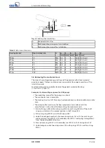
5 Installation/Dismantling
16 of 32
4K / 4KD
10.
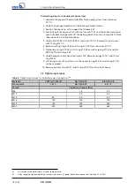
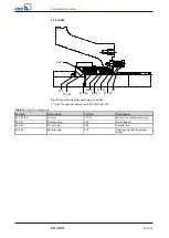
For bearing brackets P08sx, P10ax, P12sx (sizes 80, 100, 120): Fit two parallel pins
562 into the mating ring location of shaft sleeve 523.
11.
Insert O-ring 412.52 for mating ring 475.52 into shaft sleeve 523.
12.
Carefully press in mating ring 475.52.
ð
Parallel pins 562 must engage in the grooves of the mating ring.
13.
Dry and clean the seal faces again.
14.
Slide shaft sleeve 523 with mating ring 475.52 onto the pump shaft until it abuts
against the shaft shoulder.
Further installation steps for double seals
1.
Check that the seal faces are clean and free from any damage.
2.
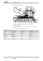
Place shaft sleeve 523 with mating ring 475.52 in a vertical position, shimmed
max.13 mm/P03ax, 17 mm/P04ax, 23 mm/P05ax-P06x, 78 mm/P08sx-P10ax-P12sx.
3.
Lift casing cover 161 with primary ring 472.51 and thrust ring 474.51. Carefully
position it horizontally above shaft sleeve 523. Lower it down, making sure that
the seal faces touch each other.
4.
Apply a suitable lubricant to O-ring 412.54.
5.
Slide disc 500.54 and spring 477.54 with O-ring 412.54 and primary ring 472.54
over the shaft sleeve.
6.
Fit mating ring 475.55 and O-ring 412.55 in seal cover 471.01.
7.
Dry and clean the seal faces. (E.g. with acetone).
8.
Insert O-ring 412.15 into seal cover 471.01.
9.
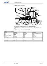
Place seal cover 471.01 on studs 902.02. Fasten the studs with nuts 920.02.
Make sure the connections are positioned correctly.
10.
Lift casing cover 161 with seal cover 471.01 and the entire mechanical seal.
Carefully slide this assembly onto pump shaft 210 and into the bearing bracket
lantern.
11.
Fasten the components with hexagon head bolts.
Installing the quench piping for mechanical seals in tandem arrangement
1.
Connect the piping for the quench supply to seal cover 471.01.
NOTE
Route the piping so as to avoid any high points. If high points cannot be avoided,
vent these points separately. Lay the pipes with a continuously rising slope. This
ensures self-venting of the pipe and and the mechanical seal.
NOTE
In order to keep the quantity and pressure in the quenched area down, installing
an orifice plate or a pressure reducer on the inlet side is recommended together
with a shut-off valve, strainer, solenoid valve and control valve.
Checking the installation
1.
Unscrew and remove one of the hexagon socket head cap screws 914 together
with compression spring 477.51 from casing cover 161.
2.
Use sliding calipers to determine the reference dimension and compare it
against the table below.
Summary of Contents for 4K Series
Page 1: ...KSB Mechanical Seal 4K 4KD For the KWP Type Series Installation Operating Manual ...
Page 30: ......
Page 31: ......


