kromo gr300 Instructions For Installation, Use And Maintenance Manual Download Page 13

EN

page 36

USER SECTION

7. OPERATION

7.1 General operation

The machine needs 3 connections to run:

• Electric;

• Water supply;

• Drain.

The machine is designed with a wash chamber inside which there is:

• A basket support, connected to a clutch equipped gear, where the rack is placed to rotate 

during the wash cycle.

• Two interchangeable wash arms where water and water mixed with granules flow from.

• A rinse arm connected to a pump which withdraws from the boiler guaranteeing constant 

temperature rinse ("Plus" system).

• A filter located under the chimney to prevent granules from rising and getting stuck in the 

fan located at the end of the chimney.

A tank is found under the chamber which contains water in one part and water mixed with 

granules in the other. The part containing water shall always be covered by blind chutes to 
avoid granule contamination. 

The part containing the granule water mixture shall always be covered by work perforated 

filters  or,  in  the  granules  recuperation  phase,  the  collection  strainer  with  special  lateral 

compensatory chutes (see chap. 7.7).

7.2 Machine preparation

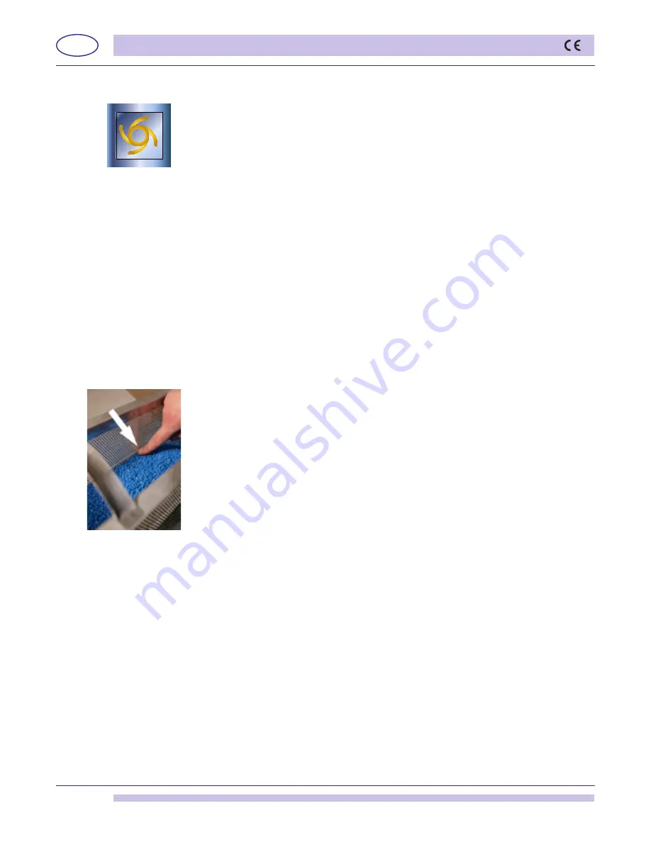
•  Prepare the right amount of granules by filling the strainer to the indicated level (see 

photo 1). 

•  Pour the contents into the right-hand side of the tank.

•  Place the overflow tube in the dedicated seat, at the tank bottom. 

•  Insert the two chutes above the water-only area (left-hand side of the tank) and the two 

perforated filters above the granule area (right-hand side of the tank).

•  The filters shall be cleaned every 15-20 cycles and whenever necessary. 

Do not use 

the machine without filters.

•  Make sure that the wash and rinse arms are properly placed.

•  Make sure that the rack support is inserted properly.

•  If the machine is equipped with a detergent dispenser, insert the transparent hose into 

the detergent canister.

•  Insert  the  special  green  rinse-aid  chemical  container  and  check  that  the  quantity  is 

sufficient for the workload of the day.

•  Shut the door.

•  Open the water valve, activate the main wall switch and proceed with turning on the 

machine by pressing key “B” (see fig. 7). The green led will come on. After a few seconds, 

the filling stage shall begin. 

•  After water-filling, the machine will automatically activate the heating stage.

•  The machine shall be ready for washing, only when the boiler and tank thermometers 

indicate that the proper temperatures have been reached: 80-85°C for the boiler and 
50-55°C for the tank.

•  Insert the rack with the various objects to wash and shut the door.

•  Before beginning the wash cycle, insert the proper detergent into the tank (if the machine 

is not equipped with an automatic dispenser).

•  Select the wash cycle time using the keys (C/D) and the type of wash cycle (only water 

or water and granule) using the keys (E/F) (see fig. 7). The green led shall come on in 

correspondence to the selected cycle (1, 2, 3, 4, 

∞)

.

•  Start the cycle by pressing key “A” (see fig. 7) Cycle start-up shall be indicated by a cycle 

selected blinking light. At the end of the cycle the light stops blinking and the word END 
appears on the display. 

•  The machine is ready for a new wash cycle.

•  It is recommended to replace the tank water with new water at least after 30 wash cycles 

or 2-3 times a day.

photo 1

Summary of Contents for gr300

Page 1: ...Instructions for Installation Use and Maintenance Istruzioni per l installazione l uso e la manutenzione EN IT COD 4000 Ed 03 11 2010 APPLICARE ETICHETTA MATRICOLA ...

Page 2: ...BOLS 35 5 1 Function keys during normal operation 35 6 FEATURES 35 6 1 General features 35 7 OPERATION 36 7 1 General operation 36 7 2 Machine preparation 36 7 3 Detergent use 37 7 4 Rinse aid use 37 7 5 Basket preparation 37 7 6 Final check 39 7 7 Granule cleaning and recuperation 39 7 8 Chamber cleaning 39 7 9 HACCP and hygiene regulations 40 7 10 Increase pressure rinse pump 40 7 11 Energy Savi...

Page 3: ... fragile objects or material which is not resistant to the washing process Do not use acidic corrosive chemical products or alkaline and solvents or chlorine based detergents Do not open the ware washer door when running The ware washer is equipped with a safety device however which will immediately shut down operation to avoid water outburst in case of accidental opening The ware washer must be d...

Page 4: ... height is 10cm 1 3 Electrical connection The electrical connection shall be carried out in accordance to the laws in force Make sure that the line voltage is the same as that written on the machine plate Apply a suitable magneto thermic omni polar switch measured in accordance to absorption and that is equipped with a contact opening of at least 3 mm always turn the machine off with this switch T...

Page 5: ...s connector B with the special connector located near the boiler injector 2 The green tube on the other hand which comes out of the suction connector C shall be inserted with a small filter and relevant ballast in the rinse aid product withdraw canister during use The connector A shall be hooked up to the rinse circuit with a T connection Initiation For initiation simply start the machine and carr...

Page 6: ...nds to 0 25 cm3 equal to 0 3 g with 1 2 g cm3 density See also par 7 3 N B A dispenser with a conductivity probe in the tank is recommended pict 5 GERMAC 15185 Ø 8 SEKO 15108 E Ø 10 pict 6 A B C A B C PROBLEM CAUSES AND REMEDY Water leaks from rins aid suction tube The suction valves 10705 D and flow do not seal due to foreign bodies is the clamping seats Clean valves 10705 D check if the rinse ai...

Page 7: ...tying boiler and break tank This function lets the boiler and break tank empty for any extraordinary maintenance or emptying function Press key B Stand By and make sure that the tank is empty Simultaneously press keys E and F granule cycle selection water cycle selection for about 5 seconds Boiler and break tank emptying is activated The display will show the message Empty during the entire emptyi...

Page 8: ...rt cycle User s Cycle Time Programming B Shut down Stand By Stop Cycle Reset Alarm C Cycle Selection D Cycle Selection E Granule cycle selection F Water only cycle selection 2 2 Function keys during programming A Programming B Exit C Increase D Decrease E Cut out F Cut out 3 FEATURES 3 1 General features The control unit managed by a microprocessor controls the following boiler water load tank wat...

Page 9: ...0 seconds Note to reset the display turn off the general wall switch for 10 seconds and then turn the main wall switch on again 4 1 Parameter selection Once parameter selection is accessed the message Pr shall be displa A repeatedly to define the parameter P number P1 P2 P20 It is now possible to modify the parameter value with the keys confirm the value or proceed to subsequent parameter programm...

Page 10: ...ergy saving threshold cycle 1 10 40 C 10 C step 1 2 C 5 Energy saving threshold cycle 2 10 40 C 15 C step 1 2 C 6 Energy saving threshold cycle 3 10 40 C 20 C step 1 2 C 7 Energy saving threshold cycle 4 10 40 C 20 C step 1 2 C 8 Water load time out 60 800 s 200s step 5s 9 Atmospheric pressure boiler load time out 100 600 s 100s step 5s 10 Energy saving enabled 0 1 1 1 enabled 11 Thermostop enable...

Page 11: ...EN page 34 INSTALLER SECTION NOTES ...

Page 12: ...y 5 1 Function keys during normal operation A Start cycle User cycle Time Programming B Shut down Stand By Stop cycle Reset Alarm C Cycle Selection D Cycle Selection E Granule cycle selection F Water only cycle selection 6 FEATURES 6 1 General features The control unit managed by a microprocessor manages the following boiler water load tank water load boiler temperature regulation tank temperature...

Page 13: ...ed every 15 20 cycles and whenever necessary Do not use the machine without filters Make sure that the wash and rinse arms are properly placed Make sure that the rack support is inserted properly If the machine is equipped with a detergent dispenser insert the transparent hose into the detergent canister Insert the special green rinse aid chemical container and check that the quantity is sufficien...

Page 14: ...le for industrial dishwashers Liquid detergent is recommended The detergent shall be placed in the tank Follow manufacturer recommendations for dosage The ware washer can be ordered with an adjustable automatic detergent dispenser Lack of detergent in this machine will cause bad wash results and clogging 7 4 Rinse aid use The machine has a standard rinse aid dispenser The machine automatically suc...

Page 15: ...shing pans of any size with handles The upper telescopic part offers easy insertion and removal e The pot stand allows washing any pot with handles f The tray stand allows the washing of 10 trays max 40mm depth While using this stand other objects may not be intruduced as they would interfere with the wash result This stand is not recommended for oven trays but for service trays with light dirt on...

Page 16: ...another or else the one behind will not be washed 7 6 Final check When the word END appears on the display the machine has finished the cycle and it is possible to open the door and remove the basket ALWAYS CHECK WASHING RESULTS MAKE SURE THAT NON GRANULES ARE ON THE OBJECTS IF SO REMOVE THEM 7 7 Granule cleaning and collection To collect the granules in the tank Remove the two filters photo 12 ph...

Page 17: ...ture when the machine is standing by for a subsequent cycle This saves energy 7 12 Thermostop function If enabled this function waits for the boiler temperature to be reached at the end of the wash cycle prolonging washing before the rinse cycle begins 7 13 Conditions that inhibiy the washing cycle The washing cycle is annulled and brought to stop position under the following conditions if fault i...

Page 18: ...cycle start The cycle is inhibited under the following conditions if the door is open in this situation the display shall read Door for 4 seconds if water is lacking in this situation the display shall read H2 O for 4 seconds when the alarm sounds during tank loading ...

Page 19: ...the machine 8 2 Extraordinary maintenance Once or twice a year have the machine inspected by a qualified technician to Clean the solenoide valve filter Remove encrustation from resistance Control the status of the seals Control for component integrity and or wear Control dispenser functioning Tighten electric connection clamps at least once a year by a service technician 9 ENVIRONMENTAL ASPECTS 9 ...

Page 20: ...d see chap 8 The disregard of the points listed above and of any the information contained in this manual can cause energy water and detergent waste with a subsequent increase in cost and or performance reduction 11 DETECTION AND DISPLAY OF ALLARMS AND FAULTS 11 1 50570 G dispaly detection The following faults are managed and displayed probes when there is a short circuit or a break or when the me...

Page 21: ...ated until the boiler temperature comes down to 105 C The cooling function is not performed or is suspended if the door is opened TYPE OF FAULT FAULT CODE SOLUTION Boiler probe fault 1 Replace probe Tank probe fault 2 Replace probe Boiler overheating 3 Probe fault control unit fault Call Service Technician Tank overheating 4 Probe fault control unit fault Call Service Technician Lack of boiler hea...

Page 22: ...ing the dispenser screw see par Rinse aid dispenser The stand is not suitable for the pots or the tools Use the suitable stand which gives the pots and tools an inclined position so that water can rinse away The washed items may have been in the wash camber too long As soon as the cycle stops remove the basket with pots and tools so that they can dry more quickly in the air Rinse temperature under...

Reviews: