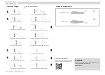
Measuring mode
Press > 2.5 s
Measuring mode
Press > 2.5 s
1
1
shows when configuring a 2 pipe installation
11/2021 - 4008317002 - OPTISONIC 6300 F/W R02 en
5
6
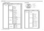
3 Installation menu X
4 Quick Setup
Select menu
Select Submenu
Functions
Status message
Tag number
X Installation
X1 language
Measured variable
X3.6 density
X3.7 temperature
X2 GDC IR interface
X3 units
Signal strength
X3.1 size
X3.2 volume flow
Operating keys
X4 pipe configuration
select
X4.1 number of pipes
X4.2 number of paths
Select menu
Select Submenu
Functions
X3.3 free unit
X3.4 [m3/s]*factor
X3.5 velocity
X5 pipe data
X5.2 diameter
X5.3 pipe material
A
Quick Setup
A1 Language
X5.4 VoS pipe material
A3.2 totalizer 1
X5.10 VoS fluid
X5.11 density
A3.3 totalizer 2
A5.1 measurement
X7.2.11 end installation
Ready? or next transducer? /
install transd. 2 /
X8._ is identical to X7._
A5.2 pulse value unit
X5.12 glycol % vol.
X5.13 dynamic viscosity
A3.4 totalizer 3
X5.14 pipe temperature
X5.5 wall thickness
A2 Tag
X5.6 liner material
X5.7 VoS liner material
A3 Reset
A3.1 reset errors
X5.8 liner thickness
X5.9 fluid
X7.2.2 number of traverses
X7.2.3 mount transducers at
A4.3 range
X7.2.4 act. flow, prelim.
X6 if pipe=2 at X4.1
X6._: identical to X5._
A4 Analog Outputs A4.1 measurement
X7
install transd. 1
X7.1 transducer set
X7.2.1 calibration number
A4.2 unit
X7.2.5 check signal
A4.4 low fow cutoff
X7.2.6 actual distance
X7.2.7 optimize distance
A4.5 time constant
X7.2.8 act.flow, prelim.
X7.2.9 path ready?
A5 Digital Outputs
X9
transducer sets
X9.1 Ta serial no.
A5.1 value p. pulse
X9.2 Ta calibration no.
X9.3 Tb serial no.
A5.1 low fow cutoff
X9.4 Tb calibration no.
X9.5 Tc serial no.
A6 GDC IR interface
X9.6 Tc calibration no.


