background image

 INSTALLATION 

2

15

OPTISONIC 3400

www.krohne.com

02/2016 - 4005026101 - QS OPTISONIC3400 MID R01 en

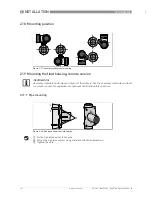
2.15  Mounting

2.16  Rotation of  the compact converter housing

Installing certified devices for hazardous areas

Installing certified devices for hazardous areas

Installing certified devices for hazardous areas

Installing certified devices for hazardous areas

- DO NOT change the position of the converter housing of compact versions
- When not following this warning, there is a very high risk of damaging the internal cables of the 
device.

Installing devices for non-hazardous areas

Installing devices for non-hazardous areas

Installing devices for non-hazardous areas

Installing devices for non-hazardous areas

Rotating the converter more than 90

°

 relative to  the sensor,   is not recommended by the 

manufacturer.

2.17  Flange deviation

CAUTION!

CAUTION!

Max. permissible misalignment  of pipe flange faces:  M

max

  0.5 degree,

 according ASME B16.5 Individual flanges. See Appendix 12 ; Flange face alignment of the 
General Piping Requirements DEP 31.38.01.11-GEN 

Figure 2-16: Flange deviation

1  

M

max

Summary of Contents for OPTISONIC 3400

Page 1: ...rasonic flowmeter for District Heating ER 3 0 1_ OPTISONIC 3400 OPTISONIC 3400 OPTISONIC 3400 OPTISONIC 3400 Quick Start Quick Start Quick Start Quick Start KROHNE 02 2016 4005026101 QS OPTISONIC3400...

Page 2: ...11 Position of pump 13 2 12 Control valve 13 2 13 Down going pipeline over 5 m 16 ft length 14 2 14 Insulation 14 2 15 Mounting 15 2 16 Rotation of the compact converter housing 15 2 17 Flange deviati...

Page 3: ...CONTENTS 3 www krohne com 02 2016 4005026101 QS OPTISONIC3400 MID R01 en OPTISONIC 3400 5 Notes 26...

Page 4: ...tions can result in damage to the device or to parts of the operator s plant INFORMATION These instructions contain important information for the handling of the device CAUTION Installation assembly s...

Page 5: ...evice will arrive in two cartons One carton contains the converter and one carton contains the sensor INFORMATION Make sure to combine the sensor and the converter correctly so they match by the devic...

Page 6: ...our measuring device is supplied ready for operation The factory settings for the operating data have been made in accordance with your order specifications The following versions are available Compac...

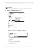
Page 7: ...nd GK information 6 Type designation of the flowmeter 7 Name and address of the manufacturer INFORMATION Look at the device nameplate to ensure that the device is delivered according to your order Che...

Page 8: ...required for operation of the subsequent devices N C connection terminals not connected Figure 2 3 Examples of nameplates on the signal converter field version 1 Ambient temperature 2 MI004 approval...

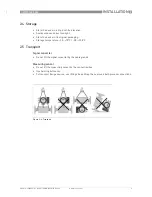
Page 9: ...nlight Store the device in its original packaging Storage temperature 50 70 C 58 158 F 2 5 Transport Signal converter Do not lift the signal converter by the cable glands Measuring sensor Do not lift...

Page 10: ...omplicated installation we kindly request you to make provisions as stated below INFORMATION The following precautions must be taken to ensure reliable installation Make sure that there is adequate sp...

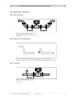
Page 11: ...Bends in 2 or 3 dimensions 2 8 3 T section Figure 2 6 Recommended inlet and outlet 1 Refer to chapter Bends in 2 or 3 dimensions 2 3 DN Figure 2 7 Inlet when using 2 and or 3 dimensional bends in fron...

Page 12: ...OPTISONIC3400 MID R01 en 2 9 Bends 2 10 Open feed or discharge Install meter on a lowered section of the pipe to ensure a full pipe condition through the meter Figure 2 9 Installation in bending pipes...

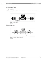
Page 13: ...ISONIC3400 MID R01 en 2 11 Position of pump 2 12 Control valve CAUTION Never install flowmeter at a pump suction side in order to avoid cavitation or flashing in the flowmeter Figure 2 12 Position of...

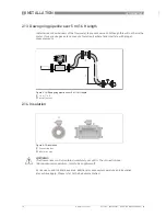
Page 14: ...olution cavitate and interfere with proper measurements 2 14 Insulation For devices used in hazardous area additional maximum temperature and insulation precautions apply Please refer to the Ex docume...

Page 15: ...llowing this warning there is a very high risk of damaging the internal cables of the device Installing devices for non hazardous areas Installing devices for non hazardous areas Installing devices fo...

Page 16: ...the signal converter to the pipe 2 Fasten the signal converter using standard U bolts and washers 3 Tighten the nuts Figure 2 17 Horizontal and vertical mounting INFORMATION Assembly materials and too...

Page 17: ...f the display 3 Pull out the display between the two metal puller devices and rotate it to the required position 4 Slide the display and then the metal puller devices back into the housing 5 Re fit th...

Page 18: ...nal regulations for electrical installations DANGER For devices used in hazardous areas additional safety notes apply please refer to the Ex documentation WARNING Observe without fail the local occupa...

Page 19: ...ns It is required for example for service to mount an external switch or circuit breaker near the device for disconnection from the mains It shall be easily reachable by the operator and marked as the...

Page 20: ...4 Laying electrical cables correctly 1 Lay the cable in a loop just before the housing 2 Tighten the screw connection of the cable entry securely 3 Never mount the housing with the cable entries facin...

Page 21: ...or connection and operation of the Ex devices 3 5 2 Description of the CG number The last 3 digits of the CG number 5 6 and 7 indicate the assignment of the terminal connections Please refer to the fo...

Page 22: ...sions This signal converter is available with various input output combinations The grey boxes in the tables denote unassigned or unused connection terminals In the table only the final digits of the...

Page 23: ...ote version Remote version Remote version Remote version a 88 mm 3 5 b 139 mm 5 5 1 c 106 mm 4 2 Total height H a 2 Compact version Compact version Compact version Compact version a 155 mm 6 1 b 230 m...

Page 24: ...i SS CS SS 25 250 155 115 27 27 8 8 32 260 156 140 35 35 9 10 40 270 173 150 39 41 11 14 50 300 193 165 53 53 14 17 65 300 203 185 63 63 18 19 80 300 238 200 78 81 17 18 100 350 268 235 102 104 24 24...

Page 25: ...imensions and weights in mm and kg Dimensions and weights in inch and lb 1 Compact housing C 2 Field housing F Version Dimensions mm Weight kg a b c d e g h C 202 120 155 260 137 4 2 F 202 120 155 295...

Page 26: ...5 NOTES 26 OPTISONIC 3400 www krohne com 02 2016 4005026101 QS OPTISONIC3400 MID R01 en...

Page 27: ...NOTES 5 27 OPTISONIC 3400 www krohne com 02 2016 4005026101 QS OPTISONIC3400 MID R01 en...

Page 28: ...ices Head Office KROHNE Messtechnik GmbH Ludwig Krohne Str 5 47058 Duisburg Germany Tel 49 203 301 0 Fax 49 203 301 10389 info krohne com KROHNE 02 2016 4005026101 QS OPTISONIC3400 MID R01 en Subject...

Reviews: