2
INSTALLATION
8
OPTISONIC 3400
www.krohne.com
02/2016 - 4005026101 - QS OPTISONIC3400 MID R01 en
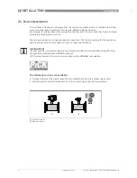
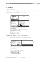
2.3.3 Examples of nameplates on the signal converter (field version)
Electrical connection data of inputs/outputs (example of basic version)
Electrical connection data of inputs/outputs (example of basic version)
Electrical connection data of inputs/outputs (example of basic version)
Electrical connection data of inputs/outputs (example of basic version)
•
A = active mode; the signal converter supplies the power for connection of the subsequent
devices
•
P = passive mode; external power supply required for operation of the subsequent devices
•
N/C = connection terminals not connected
Figure 2-3: Examples of nameplates on the signal converter (field version)
1
Ambient temperature
2
MI004 approval number and certified data
3
Tag number
4
Protection class
5
Mains supply data
6
Electronics revision number
7
Calibration, size and GK data
8
Manufacturer website
9
Type designation of the flowmeter and CE sign with number(s) of notified body / bodies
10
Name and address of the manufacturer
1
Power supply (AC: L and N, DC: L+ and L-, PE for
≥
24V AC, FE for
≤
24 VAC and DC)
2
Connection data of connection terminal D/D-
3
Connection data of connection terminal C/C-
4
Connection data of connection terminal B/B-
5
Connection data of connection terminal A/A-, A+ only operable in basic version

