background image

2

 DEVICE DESCRIPTION 

DK32 DK34

www.krohne.com

04/2015 - 4000422303  AD DK32/34 II2G R03 en

2.7  Ambient temperature / temperature classes

Due to the influence of the product temperature, variable area flowmeters with built-in electrical 
equipment (electric variants) are not assigned to any fixed temperature class. The temperature 
class of these devices is rather a function of the product temperature and ambient temperature 
that is present and the specific device version. Please see the following tables for the 
assignments.

The tables take into account the following parameters:

Ambient temperature T

amb.

Product temperature T

m

DK3./../.././../A

Ex permissible medium and ambient temperatures

INFORMATION!

The maximum permissible product temperatures listed in the tables are valid under 
the following conditions:

The measuring device is installed and operated in accordance with the installation 
instructions in the installation and operating manual.

It must be ensured that the flowmeter is not heated by the effects of additional
heat radiation (sunshine, neighbouring system components) and
thus operated above the permissible ambient temperature range.

Insulation must be limited to the piping.
Unobstructed ventilation of the indicator part must be ensured.

Temperature 
class

Ambient
temperature

Maximum permissible medium temperature
with connector (S) or cable gland (L)

Type DK32

Type DK34

[

°

C]

[

°

F]

[

°

C]

[

°

F]

[

°

C]

[

°

F]

T6

-20...+40

-4...+104

75

167

80

176

-20...+50

-4...+122

70

158

70

158

-20...+60

-4...+140

60

140

60

140

T5

-20...+40

-4...+104

100

212

100

212

-20...+50

-4...+122

95

203

100

212

-20...+60

-4...+140

85

185

90

194

T4

-20...+40

-4...+104

135

275

135

275

-20...+50

-4...+122

130

266

135

275

-20...+60

-4...+140

120

248

130

266

-20...+90

-4...+194

90

194

90

194

T3...T1

-20...+40

-4...+104

135

275

150

302

-20...+50

-4...+122

130

266

140

284

-20...+60

-4...+140

120

248

130

266

-20...+90

-4...+194

90

194

90

194

Summary of Contents for DK32 Series

Page 1: ...ical built ins Equipment category II 2 G DK32 DK34 DK32 DK34 DK32 DK34 DK32 DK34 Supplementary instructions Supplementary instructions Supplementary instructions Supplementary instructions KROHNE 04 2015 4000422303 AD DK32 34 II2G R03 en ...

Page 2: ... 1 Device description 4 2 2 Description code 4 2 3 Marking 4 2 4 Flammable products 5 2 5 Equipment category 5 2 6 Types of protection 5 2 7 Ambient temperature temperature classes 6 2 8 Electrical data 7 3 Installation 8 3 1 Installation 8 4 Electrical connections 9 4 1 General notes 9 4 2 Earthing and equipotential bonding 10 5 Operation 11 5 1 Start up 11 5 2 Operation 11 6 Service 12 6 1 Maint...

Page 3: ... with gas The EC Type Examination Certificate of the Physikalisch Technische Bundesanstalt PTB forms the basis of the EC Declaration of Conformity If required the EC Type Test Certificate can be downloaded under www krohne com 1 3 Approval according to the IECEx scheme Conformity with IECEx standards was tested in accordance with the IECEx Certification Scheme for Explosive Atmospheres as per IEC ...

Page 4: ...lized visibly with the rating plate shown below The interior of the display has an additional marking with the serial number P A 1 32 with valve and horizontal connection 34 without valve and vertical connection 2 RE inlet pressure regulator RA outlet pressure regulator 3 K1 one limit switch K2 two limit switches 4 S plug connector L cable gland incl cable 5 HT high temperature version 6 A Limit s...

Page 5: ...ding to EN 60079 11 The marking refering to ATEX is II 2G Ex ia IIC T6 T1 Gb II 2G Ex ia IIC T6 T1 Gb II 2G Ex ia IIC T6 T1 Gb II 2G Ex ia IIC T6 T1 Gb The marking refering to IECEx is Ex ia IIC T6 Ex ia IIC T6 Ex ia IIC T6 Ex ia IIC T6 WARNING Operation with flammable products is only permitted as long as no explosive fuel air mixture builds up on the inside of the flowmeter under operating condi...

Page 6: ...ditions The measuring device is installed and operated in accordance with the installation instructions in the installation and operating manual It must be ensured that the flowmeter is not heated by the effects of additional heat radiation sunshine neighbouring system components and thus operated above the permissible ambient temperature range Insulation must be limited to the piping Unobstructed...

Page 7: ... may only be connected to intrinsically safe circuits Depending on the instrument design the following maximum values apply per circuit Design DK3 A Ex Irrespective of the instrument design the following values are to be observed for each intrinsically safe circuit in case of interconnection Ui 16 VDC Ii 25 mA Pi 64 mW Ci 150 nF Li 150 µH ...

Page 8: ...observed Variable area flowmeters must be installed in such a way that There is no danger from mechanical impact effects There are no external forces affecting the indicator part The device is accessible for any visual inspections that are necessary and can be viewed from all sides The nameplate is clearly visible It can be operated from a location with secure footing CAUTION The manufacturer is n...

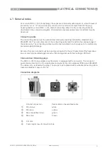
Page 9: ... sealing range of the cable entry The connecting cables must be fixed and laid in such a way as to be sufficiently protected against damage All cores that are not used must be securely connected to the earth potential of the hazardous area or carefully insulated against each other and against earth test voltage 500 Veff Cable entries Blanking plugs The DK3 S A Ex variable area flowmeter is equippe...

Page 10: ...ufficiently electrostatically grounded via the process cables an additional earth connection must be established using the earth screw 1 The position of the ground terminal is illustrated below The connection guarantees only an electrostatic connection of the device and does not comply with the requirements of an equipotential bonding connection DK32 DK34 ...

Page 11: ...ked for the proper state with regard to its installation and connection requirements The user of the system must have it checked before start up in compliance with the national regulations for checks before startup 5 2 Operation Setting of the limit switches may be carried out during operation Remove the housing cover to this purpose The housing cover has to be closed immediately after the limit s...

Page 12: ...e display part Due to the modular design of the variable area flowmeter it is possible to replace a complete display with an identical spare part in accordance with safety guidelines Exchanging the entire device Removal and installation is the user s responsibility Any replacement and removal should take place in a de energized state if possible If that is not possible the basic conditions for int...

Page 13: ...NOTES 7 13 DK32 DK34 www krohne com 04 2015 4000422303 AD DK32 34 II2G R03 en ...

Page 14: ...7 NOTES 14 DK32 DK34 www krohne com 04 2015 4000422303 AD DK32 34 II2G R03 en ...

Page 15: ...NOTES 7 15 DK32 DK34 www krohne com 04 2015 4000422303 AD DK32 34 II2G R03 en ...

Page 16: ... Analysis products Products and systems for the oil gas industry Measuring systems for the marine industry Head Office KROHNE Messtechnik GmbH Ludwig Krohne Str 5 47058 Duisburg Germany Tel 49 203 301 0 Fax 49 203 301 103 89 info krohne com KROHNE 04 2015 4000422303 AD DK32 34 II2G R03 en Subject to change without notice The current list of all KROHNE contacts and addresses can be found at www kro...

Reviews: