2
Installation and operating instruction ALTOFLUX M900 and 3080 K
Contents
System description ...................................................................................................................... 2
Product liability and warranty ..................................................................................................... 2
Standards and approvals ............................................................................................................. 3
Items included with supply........................................................................................................... 3
Handling . ...................................................................................................................................... 3
1
Important information for installation: PLEASE NOTE !....................................................4
2
Suggestions for installation ..................................................................................................5
3
Instrument nameplate ............................................................................................................6
4
Flowmeter versions................................................................................................................6
5
Installation in the pipeline .....................................................................................................7
6
Torques ...................................................................................................................................8
7
Grounding...............................................................................................................................9
8
Replacement of the separate primary head .......................................................................10
9
Technical data ......................................................................................................................12
10
Dimensions and weights .....................................................................................................14
11
Limits.....................................................................................................................................17
If you need to return flowmeters for testing or repair to KROHNE ........................................ 19
System description
ALTOFLUX electromagnetic flowmeters are precision measuring instruments designed for the
linear flow measurement of process liquids.
The process liquids must be electrically conductive:
≥
20
µ
S/cm
The
full-scale range
Q
100%
can be set as a function of the
meter size
:
ALTOFLUX M900:
DN 10 - 300 /
3
/
8
” - 12”
Q
100%
= 0.1 - 3050 m
3
/hr = 0.37 – 13 440 US GPM
ALTOFLUX 3080 K:
DN 10 - 300 /
3
/
8
” - 12”
Q
100%
= 0.1 - 3050 m
3
/hr = 0.37 – 13 440 US GPM
This is equivalent to a flow velocity of 0.3 - 12 m/s, or 1 – 40 ft/s.
Product liability and warranty
ALTOFLUX electromagnetic flowmeters are designed solely for measuring the volumetric
flowrate of electrically conductive, liquid process products.
Flowmeters with ALTOFLUX primary heads are not certified for use in hazardous locations.
Other flowmeters series are available for such applications.
Responsibility as to suitability and intended use of these electromagnetic flowmeters rests solely
with the operator.
Improper installation and operation of the flowmeters (systems) may lead to loss of warranty.
In addition, the ”General conditions of sale” forming the basis of the purchase contract are
applicable.
If ALTOFLUX flowmeters need to be returned to Krohne, please note the information given on
the last-but-one page of this manual. Krohne regret that they cannot repair or check your
flowmeter(s) unless accompanied by the completed form sheet.
Summary of Contents for ALTOFLUX 3080 K
Page 11: ...Installation and operating instruction ALTOFLUX M900 and 3080 K 11 Notes...
Page 12: ...12 Installation and operating instruction ALTOFLUX M900 and 3080 K 9 Technical data...
Page 13: ...Installation and operating instruction ALTOFLUX M900 and 3080 K 13...
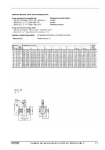
Page 14: ...14 Installation and operating instruction ALTOFLUX M900 and 3080 K 10 Dimensions and weights...
Page 15: ...Installation and operating instruction ALTOFLUX M900 and 3080 K 15...
Page 16: ...16 Installation and operating instruction ALTOFLUX M900 and 3080 K...
Page 17: ...Installation and operating instruction ALTOFLUX M900 and 3080 K 17 11 Limits...
Page 18: ...18 Installation and operating instruction ALTOFLUX M900 and 3080 K Notes...

