


Step 10, slide assembly
Slide motor holder with slide into the guides of the side parts
and fix with screw (35) in hole (C).
When installing the slider, the play in the guides should be as
low as possible but the slider can be moved without much resis-
tance.
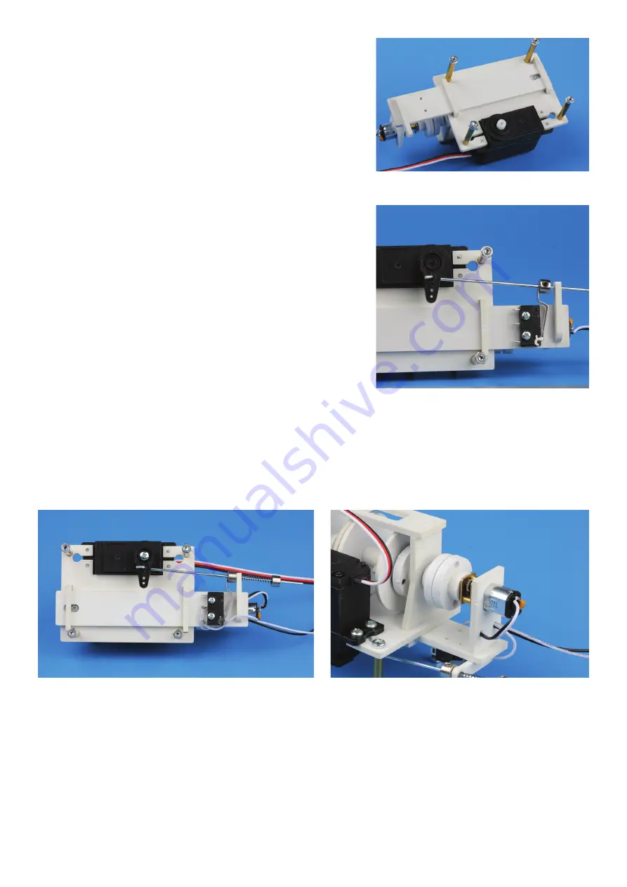
Step 11, linkage
For the cross-shaped servo lever, remove three of the four levers
and insert the linkage (32) into the smallest servo travel hole. To
do this, slightly widen the hole by hand with a 1.7 mm drill bit.
The linkage outlet must be below the servo lever. Slide a collar
(33) with set screw (34) onto the linkage. Then insert the linkage
through the hole (D) of the motor mount and mount the servo
lever on the servo on a trial basis. Hold the microswitch over the
mounting holes (E) to determine the maximum length of the
pre-bent microswitch lever.
Lever and linkage must not touch each other. Shorten the lever
with a cutting disc. Finally install the microswitch with the
screws (36).
Step 12, wiring
Feed a motor connection cable through the holes (F), (H) and (G) and solder it to pin 1 of the switch.
Solder the remaining cable to pin 2 and pass it through hole (H) from the outside. Pass the second motor
connection cable through the holes (F) and (H). Solder on the open end a 2-pin connector (not included)
for connection to power supply.
Step 13, setting and functional test
This requires a 6V power source, transmitter and receiver. Alternatively, a servo tester can be used.
1. With some force exert pressure on the two drivers with rubber buffer and tighten the grub screws
in this position. The frictional connection between the driver and the drum should only be so great
that the transmitted force of the windlass is sufficient to lift the anchor and chain. If the anchor or the
chain is jammed under water, the frictional force of the rubber buffers has created a kind of slip clutch
that prevents the model from being damaged or even being pulled under water.


