Step 6: Set operation parameters
The
VS-1616DN-MD
does not have separate output and input
buttons. Instead, the front panel includes a numeric keypad.
When the unit is powered-on, the last matrix setup that was
used is loaded. Use either the setup recall (records a stored
configuration from a preset) or default setup recall (for quick
retrieval of a commonly used programmable default setup)
functions to retrieve other setups.
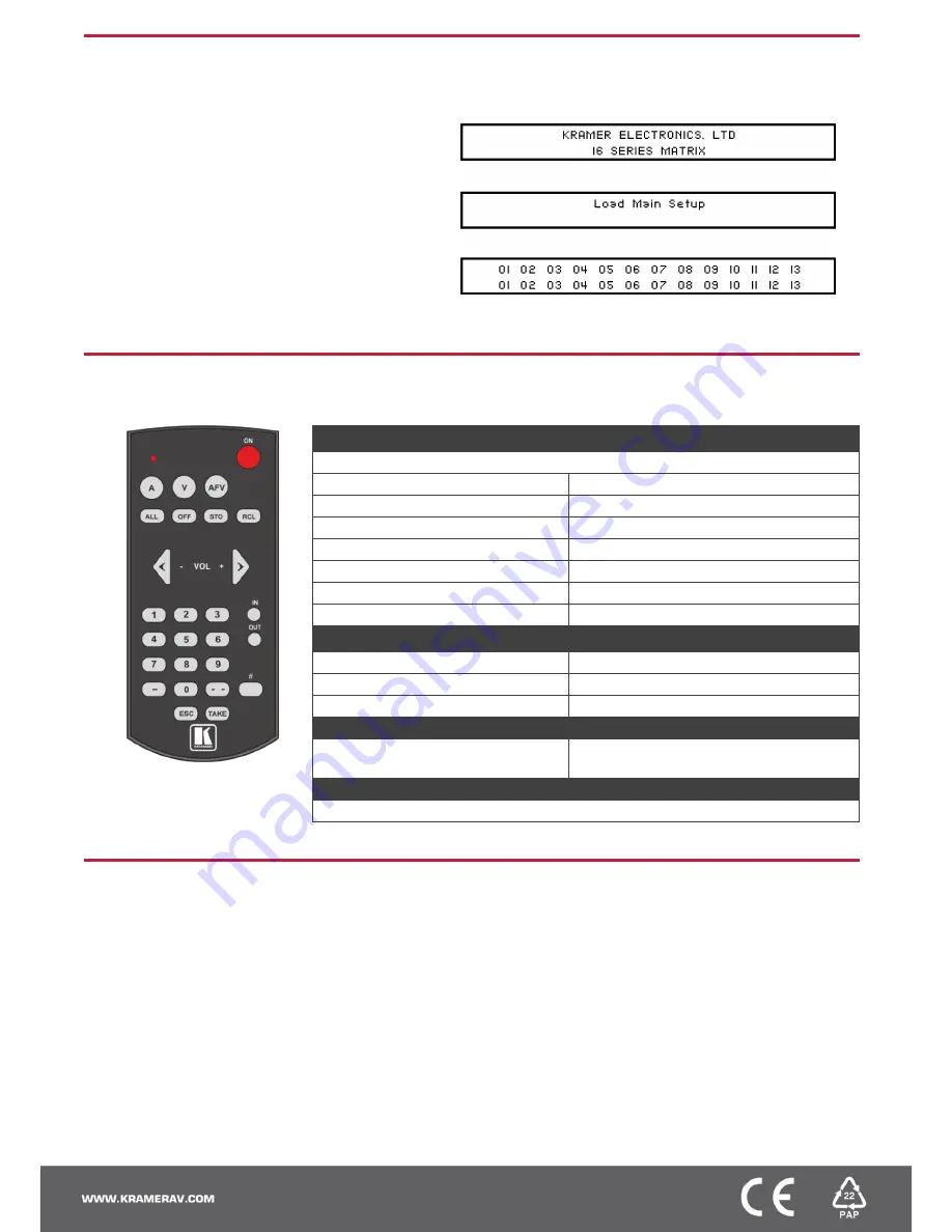
The LCD display can show only 13 out of the 16 available matrix
combinations at once. To view any of the matrix combinations
use the ◄ or the ► buttons on the front panel to shift the sliding
window to the right or left.
After switching on the power, the LCD display shows the following
screens in sequence:
Step 7: Operate via the front panel buttons and via the:
IR remote controller:
RS-232 and Ethernet:
See the
RC-IR3
user manual for
information on using the remote
controller.
RS-232
Protocol 2000/3000
Baud Rate:
9600
Data Bits:
8
Stop Bits:
1
Parity:
None
Command Format:
HEX
P2000, to switch Input 4 to Output 2:
0x01, 0x84, 0x82, 0x81
P3000, to switch Input 4 to Output 2:
#AV 4>2
Ethernet
IP Address:
192.168.1.39
TCP Port #:
5000
UDP Port #:
50000
Full Factory Reset
Front Panel
Press MENU twice. Select Total Matrix Reset >
Factory Reset. Press TAKE twice.
EDID
EDID data is passed between Output 1 and Input 1
Step 8: Set the number of input or output ports
After installing or removing a module you need to set the number of input and output ports so that the
VS-1616DN-MD
recognizes the
new configuration.
To set the number of input or output ports
:
1. Press ESC, ENTER and LOCK together. The following is displayed:
Configuration Device
2. Press ENTER. The following is displayed:
Test Board: 1 MaxInput:17 MaxOutput:17
Note:
The number of input and output ports can only be set in units of two, for example, 4 x 4, 16 x 4 or 12 x 16.
3. Using the numeric keys, enter the number of input and output ports installed. The TAKE button flashes.
4. Press TAKE. The number of installed ports is saved and the display reverts to the output/input display.
5. Reboot the device by turning the power off and then on again.