


#
Feature
Function
14
PS-1/PS-2 ERROR LED
Lights red when an error is detected. Briefly lights red immediately following a power disruption
(e.g., cable disconnection, power off, and so on).
15
TAKE Button
Press to confirm actions.
16
MENU Button
Press once to enable the ALL, OFF, STO and RCL buttons.
Press again to enter the configuration menu.
When in a Menu, press to cycle through the menu items.
17
LOCK Button
Press and hold for approximately 2 sec to lock/unlock the front panel buttons.
18
OUTPUTS/INPUTS
LCD Display
Displays the outputs (upper row) switched to the selected inputs (lower row).
Displays user interface messages and menus.
19
Front Panel Locking Screws
Release the 14 front panel locking screws to open the front panel and access the fan arrays.
20
Power Supply Thumbscrews
Release the 4 power supply thumbscrews to install / remove either of the
VS-1616DN-MD
power supplies. The
VS-1616DN-MD
can function normally with a single power supply.
21
◄ (Backward)
Press to shift the sliding window to the right (the LCD display only shows 13 cross-points out of
a total of 16).
22
1, 2, 3, 4, 5, 6, 7, 8, 9, 0
Numeric keypad, 1 to 0.
23
► (Forward)
Press to shift the sliding window to the left (the LCD display only shows 13 cross-points out of
a total of 16).
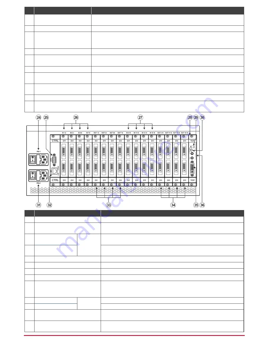
#
Feature
Function
24
PS-1 AC Mains Power Module
Power supply 1: Fuse holder and power cord socket. Connect to the AC mains supply.
25
RS-232 9-pin D-sub Port
Connects to the remote operation PC or remote controller. If the unit is not the first unit in
the line, connects to the RS-232 OUT 9-pin DB port of the previous unit in the line.
26
IN 1~8 Connectors
INPUTS
Connect to the relevant video sources, depending on the cards installed
(1 to 8).
27
IN 9~16 Connectors
Connect to the relevant video sources, depending on the cards installed
(9 to 16).
28
TEST Module
Signal generator module for testing video and audio outputs.
29
RESOLUTION DIP-switches
Set the resolution for video generated by the Test module.
30
PATTERN Button
Press the button repeatedly to change the video pattern generated by the Test module.
31
PS-2 AC Mains Power Module
Power supply 2: Fuse holder and power cord socket. Connect to the AC mains supply.
32
NET Ethernet RJ-45 Connector
Connect to a PC or controller via the Ethernet LAN.
LINK LED flashes when communication is active. POWER LED lights when the
interface receives power.
33
OUT 1~8 Connectors
OUTPUTS
Connect to the relevant video acceptors, depending on the cards installed (1 to 8).
34
OUT 9~16 Connectors
Connect to the relevant video acceptors, depending on the cards installed (9 to 16).
35
Test Module DVI Molex 24-pin Video
Connector
Connect to one of the relevant video inputs/outputs to aid in troubleshooting.
36
Test Module 3.5mm Mini Jack
Unbalanced Analog Audio Connector
Connect to one of the relevant audio inputs/outputs to aid in troubleshooting.


