background image

Using the VM-28H / VM-216H 


15 

6.4  Using the EDID Button 

Initially, the 

VM-28H


VM-216H

 operates with the factory default EDID. 

You can acquire the EDID from: 


One Output (the selected output LED blinks) 


The Default EDID (all the output LEDs blink) 


Several Connected Outputs, the Auto-mix Mode

1

To cycle between the different modes (One Output, Default and Auto-mix), 
press the input button (IN 1 or IN 2) to which you want to read the EDID, as 
defined in 

 (the output LEDs blink 

in sequence)  

Table 2

.  

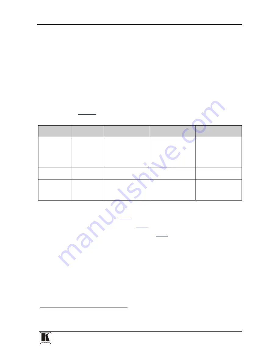
Table 2: The EDID Modes 

Current  

EDID Mode 

Appearance 

To cycle to the 

Default EDID 

To cycle to the Auto-

mix EDID 

To cycle to the One 

output EDID 

One output  

The selected 

output LED 
blinks 

Press the IN button 

once again after 
selecting output 8 (for 

VM-28H

) or output 16 

(for 

VM-216H

). The 

output LEDS blink 


Default  

The output 

LEDs blink 


Press the IN button 

once 


Auto-mix 

The output 

LEDs blink in 
sequence 


Press the IN button to 

select the required 
output. The selected 
output blinks 

To acquire or change the EDID of a new output display from: 


One output, see section 

 6.4.1


The default EDID, see section 

 6.4.2


Several connected outputs, see section 

 6.4.3


6.4.1 

Acquiring / Changing the EDID from one Output 

To acquire or change the EDID of a new output display: 

1.  Connect the power supply. 

2.  Connect the new output display device. 

3.  Press the EDID button for more than 3 seconds. 


1  The EDID acquired is a weighted average of all the connected outputs. For example, if several displays with different 

resolutions are connected to the outputs, the acquired EDID supports all the resolutions, as well as other parameters included 

in the EDID 

im Vertrieb von            CAMBOARD Electronics

www.camboard.de

Tel. 07131 911201
Fax 07131 911203

[email protected]

Summary of Contents for VM-216H

Page 1: ...tronics Ltd USER MANUAL Models VM 28H 2 Input 1 8 HDMI Distributor VM 216H 2 Input 1 16 HDMI Distributor im Vertrieb von CAMBOARD Electronics www camboard de Tel 07131 911201 Fax 07131 911203 ce info...

Page 2: ...hanging the EDID from one Output 15 6 4 2 Acquiring the Default EDID 16 6 4 3 Acquiring the EDID from several Outputs 16 7 Technical Specifications 17 8 Communication Protocol 18 Figures Figure 1 VM 2...

Page 3: ...includes the following items VM 28H and or VM 216H Power cord Infrared remote control transmitter including the required batteries and a separate user manual3 This user manual3 2 Getting Started We re...

Page 4: ...2 2 1 Quick Start This quick start chart summarizes the basic setup and operation1 1 This quick start applies both to theVM 28H and the VM 216H im Vertrieb von CAMBOARD Electronics www camboard de Tel...

Page 5: ...graphic channel1 Can read and store in non volatile memory2 the EDID3 Let you acquire the EDID from one output from several connected outputs or acquire the default EDID for fast and efficient connec...

Page 6: ...d the digital television enabling new functionality such as automatic configuration and one button play HDMI has the capacity to support Existing high definition video formats 720p 1080i and 1080p 60...

Page 7: ...ata To achieve the best performance Connect only good quality connection cables thus avoiding interference deterioration in signal quality due to poor matching and elevated noise levels often associat...

Page 8: ...ER SIMPLE CREATIVE TECHNOLOGY Your VM 28H VM 216H 6 Figure 1 VM 28H 2 Input 1 8 HDMI Distributor im Vertrieb von CAMBOARD Electronics www camboard de Tel 07131 911201 Fax 07131 911203 ce info camboard...

Page 9: ...7 Figure 2 VM 216H 2 Input 1 16 HDMI Distributor1 1 The remote IR opening item 12 is not included in this machine im Vertrieb von CAMBOARD Electronics www camboard de Tel 07131 911201 Fax 07131 911203...

Page 10: ...HDMI Connector Connects to the HDMI acceptor from 1 to 8 for the VM 28H from 1 to 16 for the VM 216H 12 REMOTE IR Opening5 Connects to an external IR receiver unit for controlling the machine via an I...

Page 11: ...om the machine This distance can be extended to up to 60 meters when used with three extension cables2 Before using the external IR receiver be sure to arrange for your Kramer dealer to insert the int...

Page 12: ...Rack with the 3 5mm connector that fits into the REMOTE IR opening on the rear panel This section describes what to do before installing in a rack and how to rack mount im Vertrieb von CAMBOARD Electr...

Page 13: ...VM 216H via RS 232 see section 6 2 Operate the VM 28H VM 216H see section 6 3 Use the EDID button see section 6 4 6 1 Connecting the VM 28H VM 216H This section describes how to connect the VM 28H see...

Page 14: ...rces for example a DVD player and a set top box to the INPUT 1 and INPUT 2 connectors respectively using the Kramer HDMI copper cables 3 If required connect a PC and or controller to the RS 232 port s...

Page 15: ...e a DVD player and a set top box to the INPUT 1 and INPUT 2 connectors respectively using the Kramer HDMI copper cables 3 If required connect a PC and or controller to the RS 232 port see section 6 2...

Page 16: ...Connect the RS 232 9 pin D sub port on your PC to the RS 232 9 pin D sub rear panel port on the VM 28H VM 216H as Figure 5 illustrates 9 pin D sub From PC 9 pin D sub Male If a shielded cable is used...

Page 17: ...216H The output LEDS blink Default The output LEDs blink Press the IN button once Auto mix The output LEDs blink in sequence Press the IN button to select the required output The selected output blink...

Page 18: ...more than 3 seconds 3 Press an input button either IN 1 or IN 2 1 once The selected input button illuminates 4 Enter the default mode as defined in Table 2 with either IN 1 or IN 2 All the OUTPUT STAT...

Page 19: ...nector OUTPUTS 8 HDMI Connectors 16 HDMI Connectors BANDWIDTH Supports up to 2 25Gbps bandwidth per graphic channel COMPLIANCE WITH HDMI STANDARD Supports HDMI 1 3 and HDCP CONTROLS EDID IN 1 IN 2 and...

Page 20: ...5 N0 2nd BYTE Bit 7 Defined as 1 I6 I0 INPUT When switching ie instruction codes 1 and 2 the INPUT 7 bits is set as the input number which is to be switched Similarly if switching is done via the mach...

Page 21: ...his is a request to identify the switcher s in the system If the OUTPUT is set as 0 and the INPUT is set as 1 2 5 or 7 the machine will send its name The reply is the decimal value of the INPUT and OU...

Page 22: ...ion orfailureto followinstructions supplied with theproduct iii Repairorattemptedrepairby anyonenot authorized byKramer iv Anyshipment oftheproduct claims must bepresentedtothe carrier v Removalorinst...

Page 23: ...of Kramer distributors visit our Web site www kramerelectronics com where updates to this user manual may be found We welcome your questions comments and feedback Caution Safety Warning Disconnect the...

Reviews: