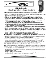
RJ-45 Pinout:
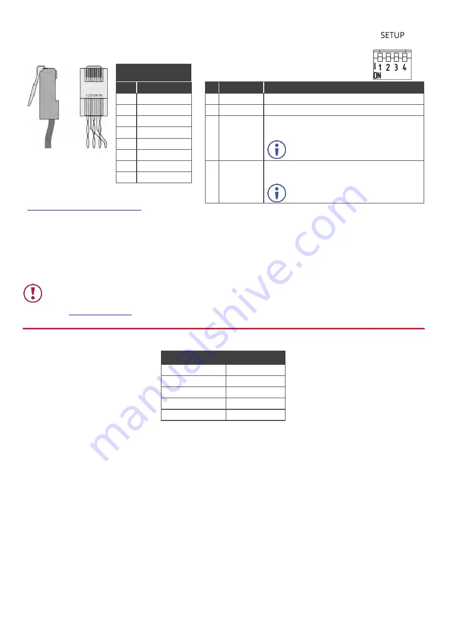
DIP-Switch Settings
For the Ethernet connector, see the wiring diagram
below:
All DIP-switches are set to OFF (up) by default.
Changes to DIP-switch 4 only take effect after
rebooting the device.
PIN EIA /TIA 568B
PIN Wire Color
# Feature
Dip-switch Settings
1
Orange / White
1 Reserved
For future use.
2
Orange
2 Reserved
For future use. Set to OFF (up).
3
Green / White
3 IR
Frequency
OFF (up) – IR frequency is 38kHz.
ON (down) – Wide-range modulated IR frequency.
4
Blue
5
Blue / White
Set to OFF for backward compatibility
with 38kHz IR extension.
6
Green
7
Brown / White
4 FW
Upgrade
OFF – Normal operation mode.
ON – HDBT FW upgrade mode.
8
Brown
For optimum range and performance use the
recommended Kramer cables available at
www.kramerav.com/product/TP-789R
When set to ON device operation is
disabled.
Step 5: Connect the power
When used as a PoE provider, connect the 48V DC power supply to
TP-789R
and plug it into the mains electricity (to also provide
power to a transmitter).
When accepting power from an HDBT transmitter via PoE there is no need to connect the 48V DC power supply.
Safety Instructions
Caution:
There are no operator serviceable parts inside the unit.
Warning:
Use only the Kramer Electronics power adapter that is provided with the unit.
Warning:
Disconnect the power and unplug the unit from the wall before installing.
for updated safety information.
Step 6: Upgrade the firmware
Upgrade the firmware by:
•
Setting the DIP-switches.
•
Loading the new firmware via
the RS-232 port on the
TP-789R
.
RS-232 Pass-through Data
Baud Rate:
115,200
Data Bits:
8
Stop Bits:
1
Parity:
None
Command Format: ASCII