253PB090 Rev.2 01/2018
www.pentair.com
IT
Originale Istruzioni per l‘uso
EN
Instruction Manual
FR
Instructions de service
DE
Betriebsanleitung
ES
Instrucciones de uso
PL
Instrukcja eksploatacji
PENTAIR
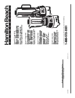
EASYBOOST
GRUPPI DI PRESSIONE CON 2 POMPE
BOOSTER SETS WITH 2 PUMPS
GROUPES DE PRESSION AVEC 2 POMPES
DRUCKAGGREGATE MIT 2 PUMPEN
GRUPOS DE PRESIÓN CON 2 BOMBAS
ZESTAW HYDROFOROWY Z 2 POMPAMI