background image

KRAMER:  SIMPLE CREATIVE TECHNOLOGY


Your SP-10D Digital Video Processor 


6

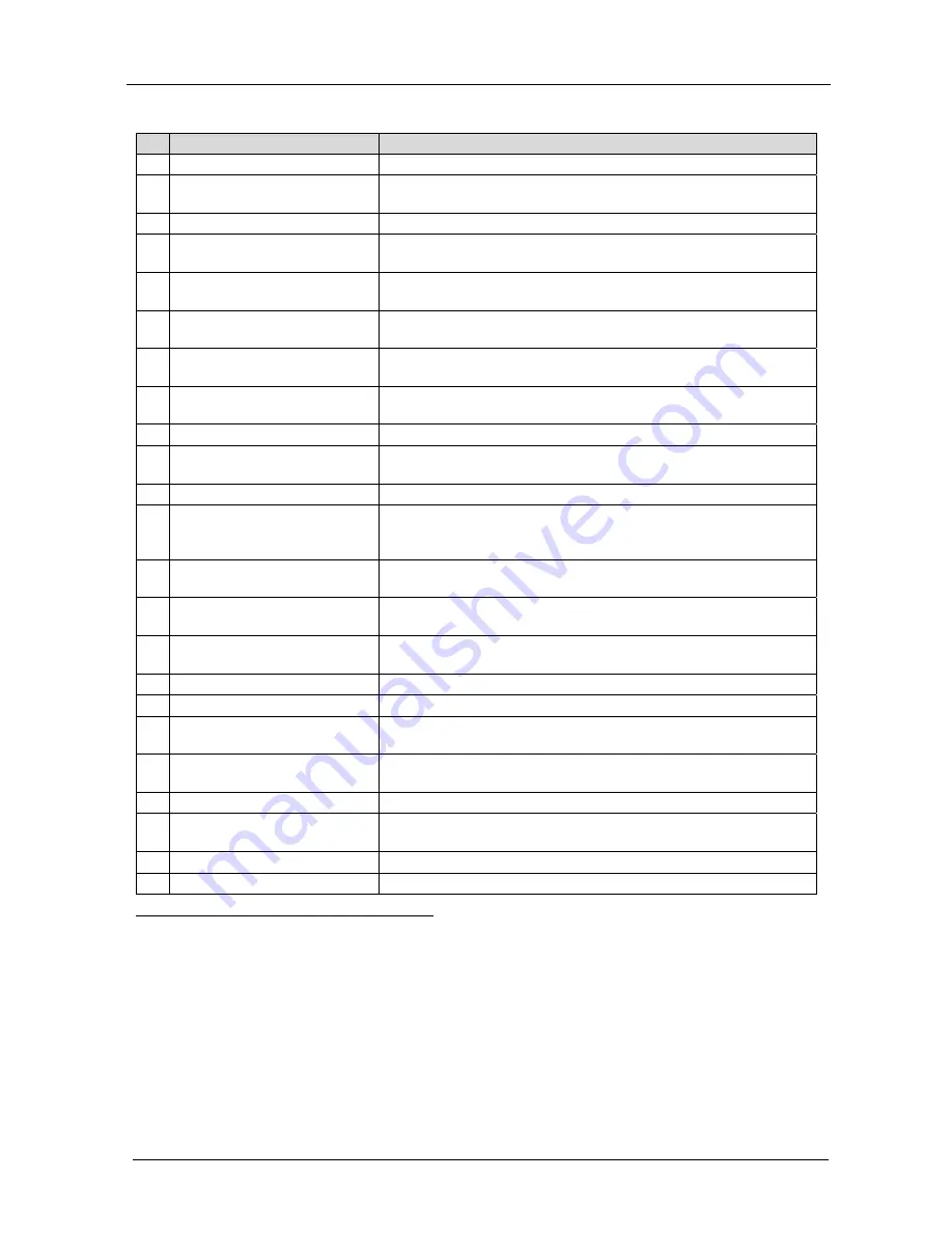
Table 1: Front Panel SP-10D Digital Video Processor 

Feature 

Function 

POWER

 Switch 

Illuminated switch for turning the unit ON or OFF 

INPUT


STANDARD 

LEDs


Cycle between PAL B, PAL N, PAL M, NTSC 3, NTSC 4, and 
SECAM. The corresponding LED lights 

INPUT

 Selector Button


Press to select the source, illuminating the appropriate LED 

INPUT

 LEDs


Cycle between the video sources: CV, YC, YUV, and RGB/S. The 
corresponding LED lights 

AUTO

 Button 

Toggles between automatically recognizing the input standard 

(lighting the appropriate LED) and the manual selection mode 

OUTPUT


STANDARD 

LEDs 

Cycle between PAL B, PAL N, PAL M, NTSC 3, NTSC 4, and 
SECAM. The corresponding LED lights 

7 (COMPONENT

) OUTPUT


Button


Selects the component video output signal 

8 COMPONENT

 OUTPUT

 LEDs Cycle between YUV, RGB, and RGBS. The corresponding LED 

lights 

9 STANDARDS


Button 

Selects the output video standard 

10 

SCH

 Button


Press the SCH button and adjust the subcarrier to horizontal 
phase relative to the genlock source, using the + and – buttons 

11 

GENLOCK

 Button


Press to enable GENLOCK operation 

12 

SPLITTER 

Button


Press the SPLITTER


button and adjust the position of the 

boundary between the edited image and the original image, using 
the + and – buttons 

13 

DELAY

 Button 

Press the DELAY

1

 button and adjust the H-delay of the output 

signal relative to the genlock source, using the + and – buttons 

14 

V-SHARP

 Button


Press the V-SHARP button and adjust the vertical sharpness 
using the + and – buttons 

15 

H-SHARP

 Button


Press the H-SHARP button and adjust the horizontal sharpness 
using the + and – buttons 

16 

BRIGHTNESS 

Button


Press the BRIGHT button and adjust using the + and – buttons 

17 

CONTRAST 

Button


Press the CONTRAST button and adjust using the + and – buttons 

18 

H-SHIFT

 Button


Press the H-SHIFT button and adjust H-Chroma-Luma delay using 
the + and – buttons to enable horizontal shifting of the image 

19 

V-SHIFT

 Button


Press the V-SHIFT button and adjust V-Chroma-Luma delay using 
the + and – buttons to enable vertical shifting of the image 

20 

GAIN 

Button


Press the VIDEO GAIN button and adjust using the +

2

 and –

3

 buttons 

21 

Y/GREEN 

Button


Press the Y

4

/GREEN

5

 button

6

 and adjust using the + and – 

buttons 

22 

COLOR 

Button


Press the COLOR

7

 button and adjust using the + and – buttons 

23 

U/BLUE 

Button


Press the U

4

/BLUE

5

 button

6

 and adjust using the + and – buttons 


1 Data delay problems, especially with long cables, occur when electronic signals travel via coaxial cable and the picture 

shifts mainly in the horizontal axis (due to unequal delays between the sync signals and data). Center the picture by pressing 

the DELAY button and adjust via the + and – buttons 

2 To add brightness 

3 To fade the picture in and out 

4 For YUV 

5 For RGB 

6 When the COLOR SPACE button is selected 

7 Pressing the + button enhances dull colors. Pressing the – button reduces distortion (snow) 

Summary of Contents for SP-10D

Page 1: ...Kramer Electronics Ltd Preliminary USER MANUAL Model SP 10D Digital Video Processor...

Page 2: ...ront Panel 14 8 Technical Specifications 15 9 Communication Protocol 16 Figures Figure 1 SP 10D Digital Video Processor 5 Figure 2 Connecting the SP 10D Digital Video Processor 10 Figure 3 Crossed Cab...

Page 3: ...SP 10D Digital Video Processor Null modem adapter Power cord2 This user manual3 2 Getting Started We recommend that you Unpack the equipment carefully and save the original box and packaging materials...

Page 4: ...KRAMER SIMPLE CREATIVE TECHNOLOGY Getting Started 2 2 1 Quick Start This quick start chart summarizes the basic setup and operation steps...

Page 5: ...corrected TBC output Individual H and V Chroma Luma delay In addition the SP 10D Digital Video Processor includes 16 non volatile memory setups that are available for saving the settings Power down sa...

Page 6: ...signal quality due to poor matching and elevated noise levels often associated with low quality cables Avoid interference from neighboring electrical appliances that may adversely influence signal qua...

Page 7: ...Your SP 10D Digital Video Processor 5 Figure 1 SP 10D Digital Video Processor...

Page 8: ...ust the H delay of the output signal relative to the genlock source using the and buttons 14 V SHARP Button Press the V SHARP button and adjust the vertical sharpness using the and buttons 15 H SHARP...

Page 9: ...Y or RGBS connect all 4 connectors G B R and S2 video source 38 R R Y BNC Connector 39 B B Y BNC Connector 40 SYNC BNC Connector Connects to the external video sync source 41 OUTPUTS SPLITTER BNC Conn...

Page 10: ...KRAMER SIMPLE CREATIVE TECHNOLOGY Installing the SP 10D in a Rack 8 5 Installing the SP 10D in a Rack This section provides instructions for rack mounting the 1U unit...

Page 11: ...PUT BNC connector to a composite video display The Y C OUTPUT 4 pin connector to an s Video display The CV OUTPUT BNC connector to a composite video display The five BNC OUTPUTS connectors G Y B B Y R...

Page 12: ...ng for example a PC A crossed cable or null modem is required as shown in method A and B respectively If a shielded cable is used connect the shield to pin 5 Method A Figure 3 Connect the RS 232 9 pin...

Page 13: ...to connect only these 3 pins or all 9 pins Figure 4 Straight Cable RS 232 Connection with a Null Modem Adapter 6 2 DIP Switch Settings The SP 10D DIP switch settings are defined in Table 3 and Table 4...

Page 14: ...ource CV YC YUV or RGB S that you want to convert The appropriate INPUT LED lights indicating selection and conversion of that source 2 When the AUTO button illuminates the video standard correspondin...

Page 15: ...digit 0 corresponds to the normal level NORM Press the button or button once to gradually increase or decrease the current level by one unit the 7 segment display shows the new level To increase or d...

Page 16: ...recall a setup do the following Press the RECALL button and then select the appropriate that corresponds to the setup by pressing the and buttons the selected setup is recalled Press the RECALL button...

Page 17: ...BNC connector 1 YC 1Vpp 75 Y 0 3Vpp 75 C on a 4 pin connector 1 component Y R Y B Y or RGB S 1Vpp 0 7Vpp 0 7Vpp 75 on BNC connectors VIDEO STANDARDS PAL B D G H I M N NTSC 3 58 4 43 SECAM DIGITAL RES...

Page 18: ...When working in HEX add 80 to the values in the table 2 When working in DEC add 128 to the values in the table 3 All values in the table are in DEC Byte 2 Command Description Byte 3 parameter value 0...

Page 19: ...RD PC I 34 D 0 E PROGRAMM NUMBER MACHINE RECALL CHANGING OTHER KEYS PC I 33 D PARAMETER NUMBER E PARAMETER MACHINE PARAMETER WRITE PC TO MACHINE RESET VIDEO POWER UP PSEUDO PC I 0 D 0 E 0 MACHINE PC I...

Page 20: ...D 1 E 0 MACHINE PC I 61 D MACHINE NAME HIGH E MACHINE NAME LOW MACHINE SOFTWARE VERSION PC I 61 D 3 E 0 MACHINE PC I 61 D SOFTWARE VERSION HIGH E SOFTWARE VERSION LOW MACHINE Examples 1 Select CV inp...

Page 21: ...ofnature ii Product modification orfailureto followinstructions supplied with theproduct iii Repairorattemptedrepairby anyonenot authorized byKramer iv Anyshipment oftheproduct claims must bepresented...

Page 22: ...or the latest information on our products and a list of Kramer distributors visit our Web site www kramerelectronics com where updates to this user manual may be found We welcome your questions commen...

Reviews: