background image

KRAMER:  SIMPLE CREATIVE TECHNOLOGY


Operating the SP-10D Digital Video Processor 


12

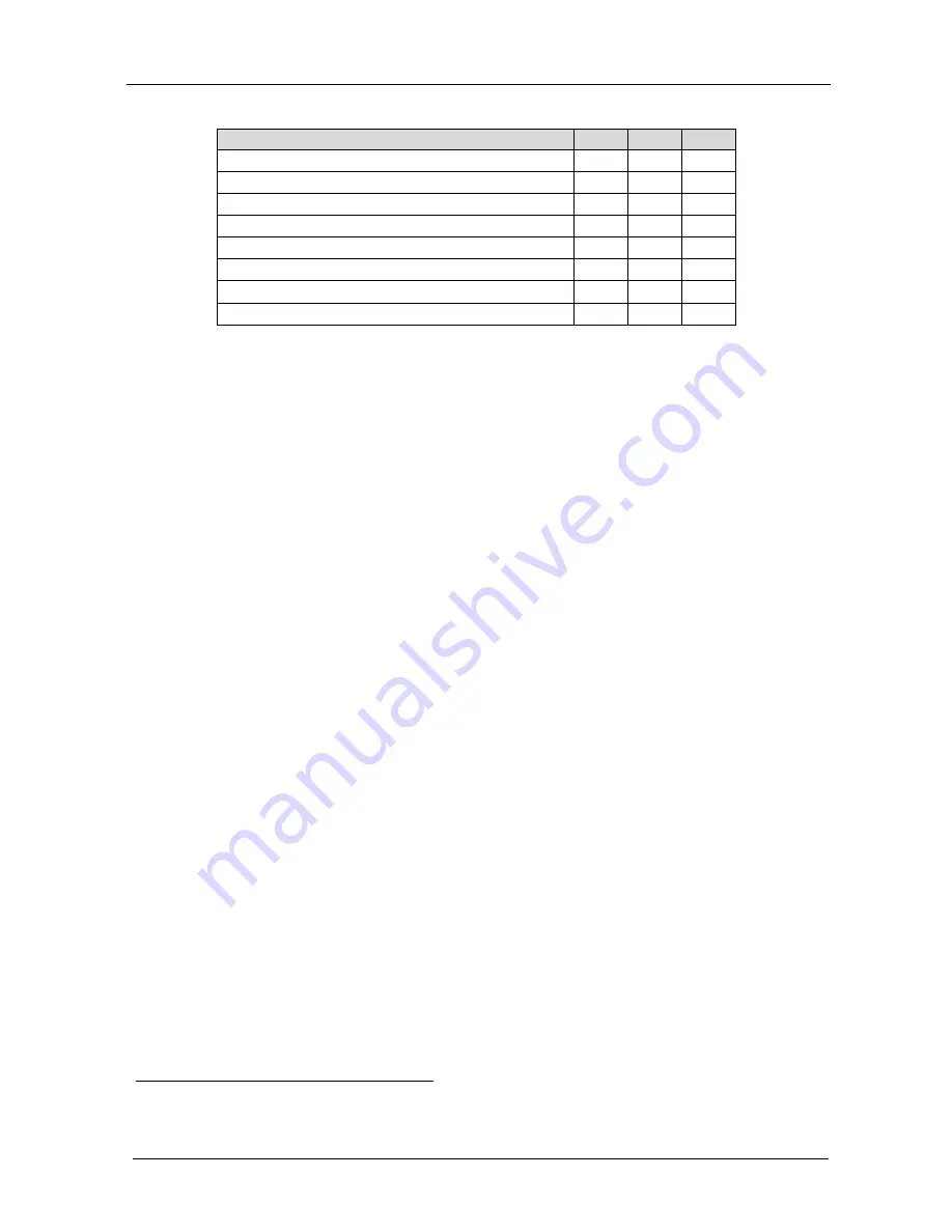
Table 4: Test Signals 

The SP-10D 

DIP 4 

DIP 5 

DIP 6 

VITS 330 (Modulated Staircase) – full field mode 

ON 

ON 

ON 

No Signal

1

 OFF 

OFF 

OFF 

Split 75% Bar Generator 

ON 

ON 

OFF 

VITS 18 (Multiburst 5.8MHz) – full field mode 

ON 

OFF 

ON 

Vertical 75% Bar Generator 

ON 

OFF 

OFF 

Inverse Horizontal 75% Bar Generator 

OFF 

OFF 

ON 

Horizontal 75% Bar Generator 

OFF 

ON 

OFF 

VITS 17 (2T, 20T, 5 Step Staircase) – full field mode 

OFF 

ON 

ON 

Operating the SP-10D Digital Video Processor 

Operate your 

SP-10D


Digital Video Processor

 via: 


The front panel buttons 


RS-232 serial commands transmitted by a touch screen system, PC, 
or other serial controller 

To operate the 

SP-10D 

using the front panel buttons, do the following:


1.  Turn on the power and after it has completed its warm up sequence, press 

the INPUT button to select the source—CV, YC, YUV, or RGB/S—that 
you want to convert. 
The appropriate INPUT LED lights (indicating selection and conversion 
of that source). 

2.  When the AUTO button illuminates, the video standard corresponding to 

the selected input is detected automatically. 
The appropriate INPUT STANDARD LED lights: PAL B, PAL N, PAL 
M, NTSC 3.58, NTSC 4.43 or SECAM

2

When the AUTO button does not illuminate—that is, the 

SP-10D

 is in 

manual mode—select the desired video standard by pressing the AUTO 
button to cycle between the various video standards. 

3.  Press the (Component) OUTPUT button to select the component output 

signal format: YUV, RGsB, or RGBS. 

4.  Press the STORE button twice to save the previous selection (power down 

saving: optional). 

5.  Press the STANDARDS button to select the output standard of the 

composite video signal. 
The appropriate OUTPUT STANDARDS LED flashes as well as the 
STORE button. However, the output standard is not altered. 


1 This is the main mode; test signals are not available 

2 For example, when the composite source is selected, the PAL B INPUT STANDARD LED lights 

Summary of Contents for SP-10D

Page 1: ...Kramer Electronics Ltd Preliminary USER MANUAL Model SP 10D Digital Video Processor...

Page 2: ...ront Panel 14 8 Technical Specifications 15 9 Communication Protocol 16 Figures Figure 1 SP 10D Digital Video Processor 5 Figure 2 Connecting the SP 10D Digital Video Processor 10 Figure 3 Crossed Cab...

Page 3: ...SP 10D Digital Video Processor Null modem adapter Power cord2 This user manual3 2 Getting Started We recommend that you Unpack the equipment carefully and save the original box and packaging materials...

Page 4: ...KRAMER SIMPLE CREATIVE TECHNOLOGY Getting Started 2 2 1 Quick Start This quick start chart summarizes the basic setup and operation steps...

Page 5: ...corrected TBC output Individual H and V Chroma Luma delay In addition the SP 10D Digital Video Processor includes 16 non volatile memory setups that are available for saving the settings Power down sa...

Page 6: ...signal quality due to poor matching and elevated noise levels often associated with low quality cables Avoid interference from neighboring electrical appliances that may adversely influence signal qua...

Page 7: ...Your SP 10D Digital Video Processor 5 Figure 1 SP 10D Digital Video Processor...

Page 8: ...ust the H delay of the output signal relative to the genlock source using the and buttons 14 V SHARP Button Press the V SHARP button and adjust the vertical sharpness using the and buttons 15 H SHARP...

Page 9: ...Y or RGBS connect all 4 connectors G B R and S2 video source 38 R R Y BNC Connector 39 B B Y BNC Connector 40 SYNC BNC Connector Connects to the external video sync source 41 OUTPUTS SPLITTER BNC Conn...

Page 10: ...KRAMER SIMPLE CREATIVE TECHNOLOGY Installing the SP 10D in a Rack 8 5 Installing the SP 10D in a Rack This section provides instructions for rack mounting the 1U unit...

Page 11: ...PUT BNC connector to a composite video display The Y C OUTPUT 4 pin connector to an s Video display The CV OUTPUT BNC connector to a composite video display The five BNC OUTPUTS connectors G Y B B Y R...

Page 12: ...ng for example a PC A crossed cable or null modem is required as shown in method A and B respectively If a shielded cable is used connect the shield to pin 5 Method A Figure 3 Connect the RS 232 9 pin...

Page 13: ...to connect only these 3 pins or all 9 pins Figure 4 Straight Cable RS 232 Connection with a Null Modem Adapter 6 2 DIP Switch Settings The SP 10D DIP switch settings are defined in Table 3 and Table 4...

Page 14: ...ource CV YC YUV or RGB S that you want to convert The appropriate INPUT LED lights indicating selection and conversion of that source 2 When the AUTO button illuminates the video standard correspondin...

Page 15: ...digit 0 corresponds to the normal level NORM Press the button or button once to gradually increase or decrease the current level by one unit the 7 segment display shows the new level To increase or d...

Page 16: ...recall a setup do the following Press the RECALL button and then select the appropriate that corresponds to the setup by pressing the and buttons the selected setup is recalled Press the RECALL button...

Page 17: ...BNC connector 1 YC 1Vpp 75 Y 0 3Vpp 75 C on a 4 pin connector 1 component Y R Y B Y or RGB S 1Vpp 0 7Vpp 0 7Vpp 75 on BNC connectors VIDEO STANDARDS PAL B D G H I M N NTSC 3 58 4 43 SECAM DIGITAL RES...

Page 18: ...When working in HEX add 80 to the values in the table 2 When working in DEC add 128 to the values in the table 3 All values in the table are in DEC Byte 2 Command Description Byte 3 parameter value 0...

Page 19: ...RD PC I 34 D 0 E PROGRAMM NUMBER MACHINE RECALL CHANGING OTHER KEYS PC I 33 D PARAMETER NUMBER E PARAMETER MACHINE PARAMETER WRITE PC TO MACHINE RESET VIDEO POWER UP PSEUDO PC I 0 D 0 E 0 MACHINE PC I...

Page 20: ...D 1 E 0 MACHINE PC I 61 D MACHINE NAME HIGH E MACHINE NAME LOW MACHINE SOFTWARE VERSION PC I 61 D 3 E 0 MACHINE PC I 61 D SOFTWARE VERSION HIGH E SOFTWARE VERSION LOW MACHINE Examples 1 Select CV inp...

Page 21: ...ofnature ii Product modification orfailureto followinstructions supplied with theproduct iii Repairorattemptedrepairby anyonenot authorized byKramer iv Anyshipment oftheproduct claims must bepresented...

Page 22: ...or the latest information on our products and a list of Kramer distributors visit our Web site www kramerelectronics com where updates to this user manual may be found We welcome your questions commen...

Reviews: