


8
SL-14RC - Defining the RC-3TB Remote Control Panel (Optional)
When configuring the
SL-14RC
with
K-Config
(version 1.0.1.X and up), you can
choose to use the K-Net port for connecting K-Net compatible user interfaces (for
example,
RC-62
/
RC-63
/
RC-53
series) or to connect to the
RC-3TB
.
If there is no K-Net auxiliary device specified in the
K-Config
control room tree,
the
K-Net
port of the
SL-14RC
will be configured to connect to an
RC-3TB
.
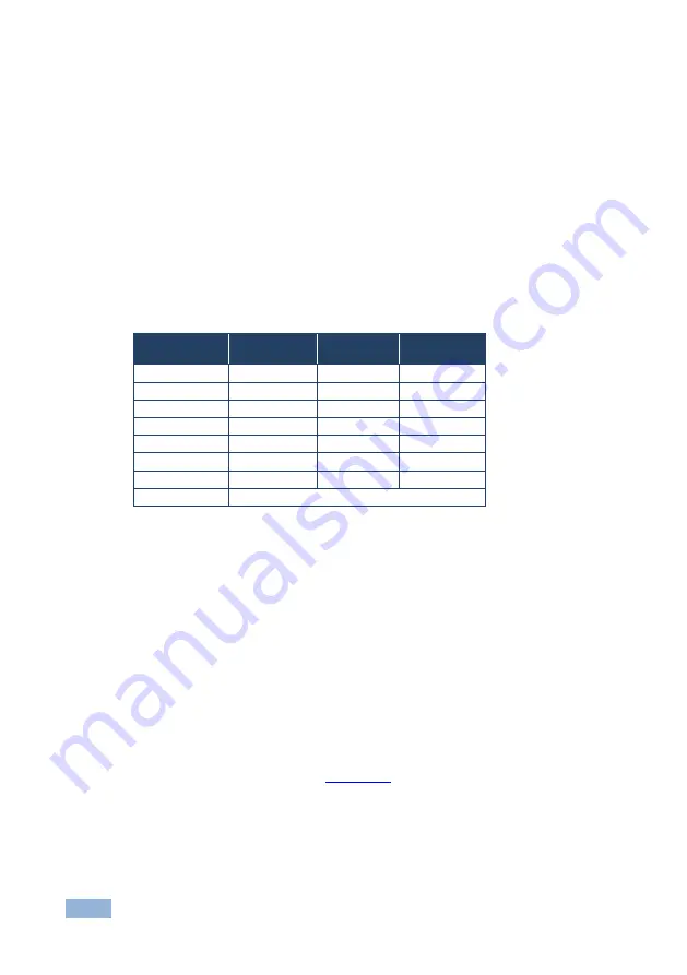
When using the
RC-3TB
, button 1 is always assigned to the second DISPLAY
button (button number 12) on the
SL-14RC
. The position of the rotary switch (in
the following table) determines which of the 12 buttons on the
SL-14RC
are
emulated by buttons 2 and 3 on the
RC-3TB
.
Rotary Switch
Position
Button 1
Button 2
Button 3
0
12
7
8
1
12
7
9
2
12
7
10
3
12
8
9
4
12
8
10
5
12
9
10
6
12
7
9
7
Service use only
For example, if the rotary switch is in position 4, the 3 buttons on the
RC-3TB
will
duplicate the functions of buttons 12, 8, and 10 on the
SL-14RC
. That is, in this
example, pressing button 1 on the
RC-3TB
has the same effect as pressing button
12 on the
SL-14RC
, pressing button 2 on the
RC-3TB
has the same effect as
pressing button 8 on the
SL-14RC
, and pressing button 3 on the
RC-3TB
has the
same effect as pressing button 10 on the
SL-14RC
.
Note:
The rotary switch configuration is only read at switch on. Therefore, when
changing the rotary switch position, you must switch off the
SL-14RC
and then
switch it on again for the new settings to take effect.
For connecting the
RC-3TB
, see
Section 6.3


