background image

22

Heating of the second circuit

Boiler is designed to supply and control two heating circuits (e.g. radiators and under-floor circuit). To control the 

second circuit (e.g. under-floor) the three-way valve has to be connected to ZIO board. 

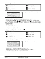
The desired temperature of the second circuit is set on 

24h temperature

 page. The 

N

 parameter is set on 

Circuit 

#2

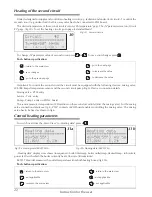
 page. (fig.30). To set the heating circuits go to page 

Extended Menu

.

30

Fig.30  Second circuit

To change 

N

 parameter value of second circuit press 

 or 

. To save your changes press 

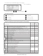
Push- buttons specification:

 – return to the main view 

 – save changes 

 – go to the previous page

 – go to the next page  

 – to increase the value 

 – to decrease the value

Instruction for the user

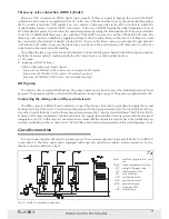
Important: To control the second circuit the circuit must be equipped with the following devices: mixing valve, 

WE-008 Kospel temperature sensor and the second circuit pump (fig.6). Devices connection details:

Mixing valve - ZTM entry
Sensor - Tco2  entry
Pump - Pump 2 entry on ZIO22 board
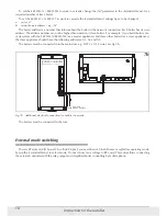
The sensor measures temperature of CH medium on the second circuit inlet (after the mixing valve). For the mixing 

valve connection details see fig.4. 

ZTM

 contacts of ZIO board enables controlling the mixing valve. The mixing 

valve has to be fixed as shown in fig.6

Central heating parameters 

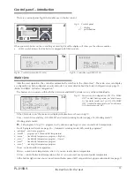
To switch over from the 

Main View

 to 

Heating data

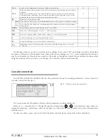
 press a 

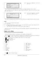
Fig.31a  Heating data (EKCO.M1z)           

31a

Heating data

 display view shows (in sequence): boiler inlet temp, boiler outlet temp, desired temp - in brackets, 

power (kW) with which the boiler currently heats, flow rate (litres/minute)

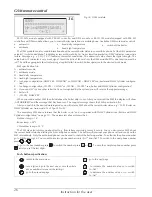
EKCO.TM model measures the outlet temperatures from both heating boxes (fig.31b).

Push- buttons specification:

 – return to the main view 

 – not applicable 

 – return to the main view

 – return to the main view 

 – not applicable 

 – not applicable 

31b

Fig.31b  Heating data (EKCO.TM)

Summary of Contents for EKCO Series

Page 1: ...ELECTRIC CENTRAL HEATING FLOW BOILER EKCO M1z EKCO M1Nz EKCO TM ...

Page 2: ...HW Cylinder configuration 13 Outdoor temperature compensation 14 Automatic summer mode 15 Working modes 16 Automatic work with 24H Temperatures weekly programming 16 Pump working mode 18 Current time setting 19 Room temperature sensor 19 DHW Pump 20 DHW cylinder 20 Heating of the second circuit 22 Central heating parameters view 22 Faults 23 Service menu 23 Boiler in cascade connection 25 GSM remo...

Page 3: ...rotected using an anti freeze liquid Basic information about the boiler The provided installation and operating instructions refers to the following boiler types EKCO M1z EKCO M1Nz EKCO TM wall mounted electric boiler single functional with the weather compensation enable to co operate with one or two central heating circuits e g radiators and under floor with the DHW cylinder and the central heat...

Page 4: ...r body with the magnetic insert chamber to the bottom Maximal pressure MPa 0 3 Minimal pressure MPa 0 05 Outflow water temperature C 20 85 Max water temperature C 100 Dimensions height x width x depth EKCO M1z mm 660 x 380 x 175 EKCO M1Nz 700 x 425 x 285 EKCO TM 815 x 503 x 197 Weight EKCO M1z kg 16 EKCO M1Nz 24 5 EKCO TM 29 Water connections EKCO M1z EKCO M1Nz G 3 4 EKCO TM G 1 Safety class IP 21...

Page 5: ... coefficient at Pod see Extended Menu on page 24 1c Special start up procedure for EKCO TM A flow rate reading error may occur if you start up the unit at low ambient temperature This error may occur because the physical properties of antifreeze solution Under this circumstances the special start up procedure will start if you activate the central heating or cylinder heating mode using the control...

Page 6: ... Instruction for the installer Pc w u circulation pump F magnetic filter NW c o CH expansion vessel NW c u w DHW expansion vessel RW expansion pipe ZB safety valve ZK cut off valve ZO air vent valve ZP straight through valve ZT thermostatic valve 3 Fig 3 Exemplary scheme of central heating system radiators under floor heating DHW cylinder DHW circuit ZZ non return valve c w u domestic hot water DH...

Page 7: ...to electrical wiring and must not be wrapped around any other wires or cables The sensor location is essential for its proper functioning Outdoor temperature sensor should be installed in the coolest place in the building north building side rela tively far away from the heat source e g windows that can be opened ventilation ducts chimneys and other heated surfaces Do not install the outdoor senso...

Page 8: ...bles The sensor location is essential for its proper functioning Outdoor temperature sensor should be installed in the coolest place in the building north building side relatively far away from heat source e g windows that can be opened ventilation ducts chimneys and other heated surfaces Do not install the outdoor sensor in the place exposed to direct sunshine Indoor temperature sensor must be lo...

Page 9: ...nsion vessel RW expansion pipe F magnetic filter ZK cut off valve 7a Fig 7a Boiler in cascade connection Three way valve connection DHW Cylinder There is a ZAS connector on ZIO22 board fig 6 page 8 If there is a need to heat up the water in the DHW cylinder the LB contact is is supplied with 230V In the case of boiler heat the water in the central heating system the LA contact is fed from 230V sup...

Page 10: ...as a master appliance and three other boilers as a slave appliances the slave appliance should have the following addresses A1 A2 and A3 The boilers must be connected into the mains use e g LIYY 2 x 0 14 wire See fig 7b 7b Fig 7b Additional electrical connection for boilers in cascade The boilers must be connected in the row External mode switching There is RP entry on ZIO board Close the RP input...

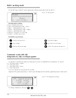
Page 11: ...e on or CH ON DHW OFF central heating mode on and domes tic hot water mode off If the CH mode is on the main view displays information as shown in fig 10 I row current time and day GG MM DT and current working mode see page 16 Working mode Working mode marks PX 24h program X e g P0 program no 0 after an equal sign you can read a 24h temperature For 24h programs details see page 16 Automatic workin...

Page 12: ...m sensor missed It s not an error as the room sensor is optional equipment Main view can show mark that inform you about the flow failure This failure is only possible when the circula tion pump is active Display view settings There are push buttons see fig 8 on control panel to set the display view and parameters After 30 seconds if you don t use any button the display view automatically returns ...

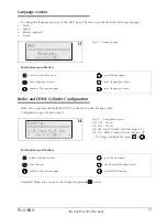
Page 13: ...turn to the main view save changes return to the previous page go to the next page on off central heating circuit on off DHW heating Language version To change the language menu go to the ABC page The menu is available in the following languages Polish English Russian optional French Fig 13 Language page 13 Push buttons specification return to the main view save language version return to the prev...

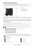
Page 14: ...der floor heating the recommended value is 8 Setting the heating curve To set N value go to Edit page see fig 16 The N value range is 4 25 Example The factory preset value of 14 informs that CH medium temperature reaches 20 C degree Tpok 20 C when Tc 76 C and Tzew 20 C Increase the N value if the room temp is too low Reduce N value in the case of rooms overheating For more information about N valu...

Page 15: ...set the outdoor temperature limit value Reaching or exceeding the limit value will switch off boiler operation automatically 17 Heating curve To change Tz value press or The controller calculates the temperature of CH medium on the basis of daily temperature and N value Push buttons specification exit key to the Main view not applicable previous page next page outdoor temperature increase outdoor ...

Page 16: ... view save changes return to the previous page Automatic work with 24h temperatures 24h weekly programs A controller is enable to load into its memory up to 4 values of estimated room temperature see fig 20 daily temperature higher daily temperature daily temperature lower night temperature You can set the above temperatures to any value Important The daily temperature must be set at the highest v...

Page 17: ...ke sure you save your changes by pressing button To build an appropriate 24 h program you have to assign daily temperatures for relevant hours There are eight 8 24 h programs loaded into controller memory You can edit 2 programs only To enter into 24 h program mode press when you are in the main view display Push buttons specification return to the main view save changes go to the next mode return...

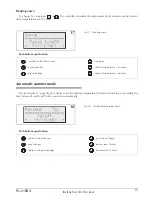
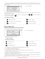
Page 18: ...ction for the user Program no 5 is editable only to set the CH medium temperature you can set a temperature the same way as for other 24h programs Week program enables to assign one of the 24h eight programs for relevant day of the week See fig 22 If you select Auto work mode the pump will stop operation in the case of a room temperature reaches the desired value b NA contacts are opened master ap...

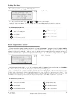
Page 19: ... Push buttons specification Hysteresis temperature range is 0 5 3 0 C A controller turns on heating operation shortly after the temperature drops below the temperature that has been set at 24hours temperature program A value of desired room temperature is displayed on the Main View see page 11 The desired temperature value includes value of hysteresis Example If the daily temperature is set at 20 ...

Page 20: ...ature in the cylinder To measure the water temperature the cylinder has to be equipped with either a thermostat or the WE 008 KOSPEL temperature sensor To set the measurement method thermostat or WE 008 sensor go to Extended Menu page For thermostat sensor wiring details see fig 6 on page 8 27 Fig 27 DHW 24h mode DHW Cylinder programming To set up a program of DHW Cylinder go to page a or b a DHW ...

Page 21: ...page Failures specification sensor disconnection failure zw sensor short circuit failure Desired temperature range 40 do 80 C Important Make sure you save your changes by pressing button Instruction for the user go to the next page to set to 1 DHW on to set to 0 DHW off Push buttons specification return to the main view save changes go to the previous page go to the next page to increase the value...

Page 22: ...mixing valve WE 008 Kospel temperature sensor and the second circuit pump fig 6 Devices connection details Mixing valve ZTM entry Sensor Tco2 entry Pump Pump 2 entry on ZIO22 board The sensor measures temperature of CH medium on the second circuit inlet after the mixing valve For the mixing valve connection details see fig 4 ZTM contacts of ZIO board enables controlling the mixing valve The mixing...

Page 23: ...ication Tz outdoor sensor Tp room Tco we inlet boiler sensor Tco wy outlet boiler sensor Push buttons specification return to the main view not applicable go to the previous page Instruction for the user go to the next page next failure not applicable Extended menu Extended Menu settings can be changed by qualified person only To edit Extended Menu go to Extended Menu code page fig 33 and enter th...

Page 24: ...s that there is no symmetry failure Parameter value is 0 for single phase boilers zew_t outdoor temperature reading intervals min 0 indicates the reading for every sec 1 indicates the reading for every minute 10 10 pok_t room temperature reading intervals min 0 indicates the reading for every sec 1 indicates the reading for every minute 5 5 ZG_MOC power of the heating box NS number of heating elem...

Page 25: ...r kw with which the boiler currently heats current rate of flow litres min Tc2_0 second circuit temperature in the case of outdoor sensor failure 50 Tc2_d Higher parameter value will affect more delay for the three way valve opening and closing operation In the case of the three way valve outlet oscillation valve opens or closes too quick and outlet temperature oscillation then increase the parame...

Page 26: ... boiler skip it over After you received the SMS the display will show AUTHORIZED and the message that has been sent The support message shows the SMS specification list After you switch to the desired working mode you will receive SMS about the current boiler status e g 15 42 Boiler on DHW Cylinder on Auto mode Tz 1 Tp 24 Tc 55 The exemplary SMS above informs that the boiler is on and co operates ...

Page 27: ...mode off 12 Fig 13 Language page 13 Fig 14 Configuration view 13 Fig 15 Heating curve 14 Fig 16 Heating curve edit page 14 Fig 17 Heating curve 15 Fig 18 Outdoor temperature limit 15 Fig 19 Working mode 16 Fig 20 24h temperatures settings 16 Fig 21 24h program 17 Fig 22 Week program 18 Fig 23 Pump working mode 18 Fig 24 Time 19 Fig 25 Hysteresis 19 Fig 26 DHW Pump 20 Fig 27 DHW 24h mode 20 Fig 28 ...

Page 28: ...KOSPEL S A ul Olchowa 1 75 136 Koszalin tel 48 94 346 38 08 info kospel pl www kospel pl ...

Reviews: