background image


Reference Guide


156


5A Preset Data Load


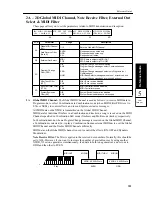
These parameters allow you to load 100 Combinations, 100 Programs, two Drum Kits of Preset a 
or b, preset Multi Setup data, and preset Global data into the internal memory.

Use the [


], [®], [


], and [


] keys to select data to load, move the cursor to “OK?”, and press 

the [


] key to load. (The existing data in the internal memory will be overwritten and lost.)

The following data can be loaded:

Preset a:

100 Programs of Preset a
100 Combinations of Preset a
Drum Kits 1, 2 of Preset a

Preset b:

100 Programs of Preset b
100 Combinations of Preset b
Drum Kits 1, 2 of Preset b

Multi Setup data:

Default settings when the power is turned on (see page 114)

Global data:

Master tune .......................... 0
Transpose............................. 0
Velocity Curve ..................... 3
After Touch Curve ............... 3
Scale Type............................ Equal Temp
Scale Key ............................. C
User Scale ............................ –52 for E and B, 0 for others
Sub Scale Type .................... User Scale
Sub Scale Key...................... C
MIDI Global channel........... 1
Note Receive........................ ALL
External Out Select ............. MIDI
MIDI Filter .......................... NUM for PRG, DIS for EX, ENA for others


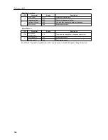
LCD

Parameter

Range

Description


5A

Preset Data Load 
Source

ALL
Combination (CMB)
Program (PRG)
Drum Kit (KIT)

Select a preset data source to load.
Loads all data of Preset a or b, Multi data, and Global data.
Loads one Combination of Preset a or b.
Loads one Program of Preset a or b.
Loads one Drum Kit of Preset a or b.

Source ALL

PER-a, PER-b

(When ALL is selected:)
Loads either Preset a or b, Multi Setup data, and Global data.

Source PRG/CMB

a, b

(When CMB or PRG is selected:)
Selects Preset a or b as a source.

Source No. 
PRG/CMB

00–99

(When CMB or PRG is selected:)
Selects a source Program/Combination number.

Destination No. 
PRG/CMB

00–99

(When CMB or PRG is selected:)
Selects a destination Program/Combination number.

Source KIT

a, b

(When KIT is selected:)
Selects Preset a or b as a source.

Source No. KIT

K1, K2

(When KIT is selected:)
Selects a source Drum Kit number.

Destination No. KIT

K1, K2

(When KIT is selected:)
Selects a destination Drum Kit number.

OK to Load

OK?

Executes the Preset Data Load operation.

05A PRESET DATA
ALL

PRE-b

OK?

5A

Summary of Contents for X5DR AI2 SYNTHESIS MODULE

Page 1: ...GENERAL INSTRUMENT AI 2 SynthesisSystem 1 E Owner s Manual AI 2 SYNTHESIS MODULE ...

Page 2: ...ments once they pass through a powerful VDF filter and VDA amplifier You can also add a rich expressiveness to a performance by altering the sound using the key touch velocity or by adjusting the brightness of the sound or the depth of the vibrato using MIDI modulation messages Rich large scale ensembles with 64 voice polyphony The X5DR s 64 voice polyphonic capability allows you to create complex...

Page 3: ...to the sound Each Program and Combination can have its own effect settings A wide range of scale types accommodates numerous musical genres In addition to the conventional equal temperament and pure temperament types of tuning a wide variety of scales is also available These scales include the Werkmeister III Kirnberger III Arabic and Indonesian scales These scales cover a broad range of musical g...

Page 4: ...lay mode will toggle between Bank A and Bank G Pressing this button in Program Edit mode Combination Edit mode Multi mode or Global mode will change the page shown on the LCD Press the PAGE button to select the next page press the PAGE button to select the previous page 5 10 button 10 button The 10 and 10 buttons increment and decrement the Program and Combination numbers in steps of 10 in Program...

Page 5: ...r the button to cancel 7 GLOBAL MULTI button Press this button to enter Multi mode or Global mode This button also switches the mode between Multi mode and Global mode In Multi mode the indicator lights up in Global mode the indicator flashes 8 EDIT button In Program Play mode press this button to select the Program Edit mode In Combination Play mode press this button to select the Combination Edi...

Page 6: ...4 inch phone jack connections should be connected to the inputs of a powered monitor stereo amplifier mixer or multi track tape recorder Use the L MONO connection for mono playback 4 TO HOST This connection is used to connect a computer to the X5DR via an optional cable AG 001 002 003 This enables you to play the X5DR via a connected computer Note Do not use adapters other than the AC adapter that...

Page 7: ...Controls vi ...

Page 8: ...s 7 Combination Examples 8 Using a Computer Sequencer Connections 9 Connecting a computer or sequencer 10 Connection via MIDI 11 Connecting an IBM PC Compatible Computer 12 Connecting an Apple Macintosh Computer 13 Settings Required When a Computer is Connected 14 Listening to a Demo performance 15 Playing the X5DR in Multi Mode Playing Back GM Scores 16 Structure of Multi Mode 17 Selecting a Trac...

Page 9: ...ous modes 31 Received MIDI data 32 Performance Functions 34 Keyboard Velocity 34 Pitch Bend Modulation Wheel 34 Effect Dynamic Modulation 35 After Touch 35 3 Editing Basic Concepts 36 Sound Structure 36 EG and MG 37 Editing Programs 38 Before Editing 38 Checking the Sound While Editing 39 Adjusting the Attack of Programs 40 Adjusting the Decay 41 Adjusting the Release 42 Adjusting the Tonal Bright...

Page 10: ...Instruments 60 Changing the Key Velocity Sensitivity 60 Changing the Note Range 60 Adjusting Effects while Playing 60 Changing the Sequence of Programs or Combinations 60 Combining Multiple Programs 60 Changing the Controller Functions in Combinations 61 Playing the Keyboard in Split Mode 61 Selecting a Particular Sound Quickly 61 Using a Different Scale 61 Editing Applications 62 Editing the Soun...

Page 11: ...ror Messages 161 Specifications 161 Options 161 MIDI Data Format 163 Program Change and Bank Select Reception in Combination Play Mode 172 PC Interface Technical Information Chart 172 MIDI Panpot Send Data 173 Wiring Diagram of Dedicated Connecting Cables 173 Installing and Setting Up the KORG MIDI Driver 174 Installing the KORG MIDI Driver in MS Windows 174 Setting Up the KORG MIDI Driver Windows...

Page 12: ...ibed in the Start up Guide This chapter also explains how to edit Programs to create new sounds Refer to this chapter to make the best use of the versatile functions and various sounds of the X5DR Reference Guide This chapter explains the function of each mode and the parameters of the X5DR in detail About MIDI This manual assumes that you have a basic knowledge of MIDI If you are using a synthesi...

Page 13: ...About this manual xii ...

Page 14: ...he MIDI keyboard to the MIDI IN jack of the X5DR using a MIDI cable Refer to MIDI keyboard settings page 2 Powered monitor stereo amplifier In order to playback the X5DR s high fidelity sound we recommend that you connect the X5DR to powered monitors i e speakers with built in amplifiers such as the optional PM 15 If you are going to connect a stereo amplifier or other device such as a stereo radi...

Page 15: ...mit channel in other words if its MIDI channel is fixed set the Global MIDI Channel on the X5DR to the same number as the MIDI transmit channel on the MIDI keyboard MIDI transmit filter MIDI keyboards allow you to transmit various MIDI data The X5DR can receive the following MIDI messages Note On Off Note message Very basic message for keyboard performance Program Change message Changes Programs C...

Page 16: ...1 Demo Song 1 AROUND THE WORLD Demo Song 2 WE VE GOT DREAMS The X5DR will play back Demo song 1 then Demo song 2 Press the COMBI button to playback Demo song 1 Press the PROG button to playback Demo song 2 To listen to playback If you wish to stop the demo song press any button To stop playback The X5DR will repeat playback of Demo songs 1 and 2 Press the EDIT button to play demo songs 1 and 2 con...

Page 17: ...s or decrements a Program number by 10 Pressing the 1 or 1 button repeatedly increments or decrements a Program number by 1 The X5DR has 100 Programs in Bank A A00 99 and 136 Programs in Bank G G01 136 for a total of 236 Programs Bank A A00 99 Bank G G01 136 Changing Programs 2 3 When you wish to change Programs from a connected MIDI keyboard or external MIDI device you must send Program Change me...

Page 18: ...heck the MIDI FILTER setting on page 2C Global mode See page 152 Program Examples The X5DR has 100 Programs A00 99 in Bank A and 136 Programs G01 136 in Bank G Play and listen to a variety of Programs The following Programs exemplify the unique sound of the X5DR Take a listen to the following Programs A01 X Piano This acoustic piano sound simulates a real piano even the sound produced when the ham...

Page 19: ...X This fantastic synth sound combines the soft sound of a female chorus with a sparkling tremolo like sound Combine different types of sounds for interesting variations and expand your collection of creative sounds The Programs described above represent only a few of the Preset a Programs Try several different Programs and enjoy the great sounds of the X5DR About Drum Kits The following Programs u...

Page 20: ...ng Combinations 2 3 Combination name Combination number Programs used for Timbres 1 4 Programs used for Timbres 5 8 The mark appears for Timbres 5 8 00 SolarFlare A30 A99 A19 A39 00 SolarFlareX A78 OFF A70 A28 COMBI What is Combination You can play Combinations in Combination Play mode Press the COMBI button to enter Combination Play mode A Combination is a sound that consists of up to eight Progr...

Page 21: ... Programs 39 Hell As you might guess from the name this is a weird sound that combines multiple drum sounds and uses effect sounds such as voices You can combine Drum Programs drum and effect sounds that are assigned to keys with normal Programs allowing you to easily create sounds with various characteristics The next Combination 40 Heaven is a unique contrast Listen to and compare these two Comb...

Page 22: ...ia MIDI and Computer interface cable Refer to page 10 13 for details Powered monitor stereo amplifier In order to play back the X5DR s high fidelity sound we recommend that you connect the X5DR to powered monitors speakers with built in amplifiers such as the optional PM 15 If you are going to connect an audio stereo amplifier or other device such as a stereo radio or a cassette tape recorder use ...

Page 23: ... 12 Connecting an Apple Macintosh using a computer interface cable Connecting an Apple Macintosh Computer on page 13 Connecting a computer By connecting a computer to the X5DR using a computer interface cable you can play the X5DR sound from the computer In addition you can control other connected MIDI devices from the computer using the X5DR as a MIDI interface You may connect the following types...

Page 24: ...ce data from the computer or sequencer you do not have to connect the MIDI keyboard If you wish to connect an additional MIDI device connect it to the MIDI OUT jack of the sequencer or computer MIDI interface or to the MIDI THRU jack of the X5DR Refer to About MIDI on page 65 for information on connections using the MIDI THRU jack Refer to the manual that comes with the MIDI interface for informat...

Page 25: ...cer software Application software that is not compatible with Windows MME Multimedia Extensions or Windows 3 1 except for those specifically supporting the X5DR cannot be used with this connection If the computer has a 25 pin serial port use an optional AG 004 9 to 25 pin adapter Set 0D PC I F CLK of the Global mode to 38 4kBPS see page 14 If you use this connection withWindows MME orWindows 3 1 y...

Page 26: ... the model of the computer or the type of sequencer software If your sequencer software has a clock setting set the clock to 1MHz Set 0D PC I F CLK of the Global mode to 31 25kBPS See page 14 Installing the Korg MIDI Driver allows the X5DR to output data from its internal tone generator separately from MIDI OUT data This makes it possible to use the X5DR as a MIDI interface for other connected dev...

Page 27: ...Global Mode 1 Press the GLOBAL button to enter Global mode The GLOBAL button allows you to switch between Global mode and Multi mode When the X5DR is in Multi mode the indicator lights up press the GLOBAL button again to enter Global mode the indicator flashes 2 Press the PAGE or PAGE button to select 2A MIDI GLOBAL 3 Press the button twice to display 2B EXT OUT SEL 4 Use the and buttons to assign...

Page 28: ...E 10 1 Demo Song 1 AROUND THE WORLD Demo Song 2 WE VE GOT DREAMS The X5DR will play back Demo song 1 then Demo song 2 Press the COMBI button to playback Demo song 1 Press the PROG button to playback Demo song 2 To listen to playback If you wish to stop the demo song press any button To stop playback The X5DR will repeat playback of Demo songs 1 and 2 Press the EDIT button to play demo songs 1 and ...

Page 29: ...ams assigned to 16 tracks When you turn on the power to the X5DR Multi mode uses a default GM setting which allows you to play back a GM score GM performance data right away If you wish to restore the GM default setting send the GM System On message or set 23A SET TO GM accordingly If the GM score is not played back correctly refer to Notes on playing back GM scores on Page 18 GLOBAL MULTI When yo...

Page 30: ... Program Change message following a Bank Select message The following Programs G01 128 are different than Programs G129 136 in terms of their response to Bank Select messages Program numbers used to select a Drum Program G129 136 in the Drum Program Bank Transmit functions and operations for Bank Select messages and Program numbers are different depending on the type of connected sequencer or sequ...

Page 31: ... Notes on Playing Back GM Scores Before playing back performance data GM scores for a GM tone generator make sure that the following settings have been made in Global mode for correct playback See page 146 for the function of each parameter Set all the parameters in Multi mode to their default setting To do so use 23A SET TO GM see page 114 or transmit a GM System On message from a computer or seq...

Page 32: ...ort Some Windows sequence software may transmit MIDI data via MIDI mapper If you are using this type of software use the MIDI mapper on the control panel to change the port name of all the MIDI channel maps to KORG PC I F Synth Port If Programs or Performance Sound Wrong If the Program sounds wrong during the playback of the GM score the GM score may be using the Bank Select message In this case s...

Page 33: ...t a and b and select PRE a or PRE b Move the cursor using the and buttons and set the parameter using the and buttons 4 Move the cursor to OK and press the button Press the button again in response to the message Are You Sure OK In the example above the loading source is set to ALL However you can select different sources Refer to page 156 EDIT GLOBAL MULTI PAGE 10 1 COMBI PROG BANK PAGE 10 1 Pres...

Page 34: ... MIDI keyboard or computer so that its MIDI transmission channel will match the X5DR Global MIDI Channel Set the X5DR Global MIDI Channel in 2A MIDI GLOBAL in Global mode see page 151 Basic operation in Program Play mode Press the PROG button to enter Program Play mode to play Programs You can switch Programs in Program Play mode by operating the front panel of the X5DR or by sending MIDI data fro...

Page 35: ...to select a Drum Program G129 136 in the Drum Program Bank Transmit functions and operations for Bank Select messages and Program numbers are different depending on the type of the connected MIDI keyboard Refer to your MIDI keyboard manual for detailed operational information Program Bank MIDI Bank Select Bank A A00 A99 CTRL 0 0 CTRL 32 0 Bank G G01 128 CTRL 0 56 CTRL 32 any number Drum Program G1...

Page 36: ...2 Pitch2 MG VDF2 EG VDA2 EG Effects Pan A B Send C D Send C D Pan A B L MONO R Double Oscillator mode only Audio signal Control signal Program Edit mode allows you to modify the sound of Programs The figure shows the structure of a Program You can create your own sound and modify its tonal color by modifying these parameters in Program Edit mode EDIT GLOBAL MULTI PAGE 10 1 COMBI PROG BANK PAGE 10 ...

Page 37: ...re Each Timbre in a Combination has MIDI filters for MIDI message such as Program Change Damper Hold 1 After Touch and Control Change Therefore MIDI data for which the MIDI filter is set to D Disable will be ignored See page 104 Basic operation in Combination Play mode Press the COMBI button to enter Combination Play mode to play Combinations You can switch Combinations in Combination Play mode by...

Page 38: ...rful in live performance Settings that determine the combination of Programs are made in Combination Edit mode See Editing Combinations on page 51 Let s take a look at the various types of Combinations that are available Layer The X5DR produces the sound of multiple Programs simultaneously When Timbres are layered together they produce a thick and complex Combination such as a piano sound overlapp...

Page 39: ...ode In Combination Edit mode use the PAGE and PAGE buttons to switch the pages use the and buttons to move the cursor flashing line and select a parameter and use the and buttons to set the value Refer to Editing Combinations page 51 for information on how to edit Combinations and refer to 2 COMBINATION Parameters page 100 for information on the parameter functions Layer Program A Program B Multip...

Page 40: ... Multi mode When the X5DR is in Global mode the indicator flashes press the MULTI button again to enter Multi mode You can change each track s settings by means of message sent from the front panel or from an external MIDI device Editing on the unit Use the PAGE and PAGE buttons to switch pages use the and buttons to move the cursor flashing line and select a parameter and use the and buttons to s...

Page 41: ...Track Track 10 will ignore CTRL 91 93 and its Send C D setting for each index if a Drum Kit is used since P is the default setting for Track 10 However if the Send C D setting for Track 10 is set to any value other than P this Track will respond to the received Send C D message That is the Send C D setting for all the indexes in the Drum Kit will become the same About Transpose Detune and Pitch Be...

Page 42: ...again to enter Multi mode Use the PAGE and PAGE buttons to switch the pages use the and buttons to move the cursor flashing line and select a parameter and use the and buttons to set the value Refer to 5 Global Parameters page 146 for each parameter function in Global mode EDIT GLOBAL MULTI PAGE 10 1 COMBI PROG BANK PAGE 10 1 Press the GLOBAL button The indicator flashes 00A MASTERTUNE ø Tune 00 4...

Page 43: ...hen EXT OUT SEL is set to PCIF the data is not output from the MIDI OUT connector This connector also outputs MIDI data of the KORG PC I F MIDI Port received at the TO HOST connector When 4A MIDI DUMP is selected in Global mode the signal is transmitted to the destination specified in 4A See page 154 TO HOST connector Connecting the TO HOST connector and a computer using a computer interface cable...

Page 44: ...DI Channel on 2A MIDI GLOBAL in Global mode See page 151 Combination Play mode In Combination Play mode data is played on the MIDI receive channel of each Timbre Sending Program Change and Bank Select messages will change the Program used for the respective Timbres You can change the Combinations by sending Program Change messages on the Global MIDI Channel Set the Global MIDI Channel on 2A MIDI G...

Page 45: ... notes 0 127 sound pitch However some note ranges might not play depending on the particular Program Program Change This message changes the Programs In Program Play mode and Multi mode it changes the Programs within the same Bank In Combination Play mode sending this message changes Programs on the Timbres MIDI channel and it changes Combinations on the Global MIDI Channel Use the Bank Select mes...

Page 46: ...s also used to edit the Programs along with Exclusive data Volume CTRL 7 This message adjusts the volume level In particular this is primarily used to adjust the volume balance between the Timbres Tracks Pan CTRL 10 This message sets the panpot A B only in Combination Play mode and Multi mode Expression CTRL 11 This message adjusts the volume level In particular it is used to change the volume lev...

Page 47: ...ound and playing hard will produce a loud sound In addition you can also adjust the brightness of the sound and the envelope settings such as the attack rate and release time Using Velocity Switch in Combination Play mode and Multi mode you can play different Programs by changing the keyboard velocity See page 91 93 for information on how to change the volume level and envelope using key velocity ...

Page 48: ...formation on adjusting real time effect parameters After Touch While you play the keyboard pressing the keys harder will control tonal brightness or modulation See page 95 for information on adjusting the depth of vibrato using After Touch See page 97 for information on adjusting the depth of wah using After Touch See page 97 for information on adjusting the pitch using After Touch See page 97 for...

Page 49: ...e Digital Filter block and volume by the VDA Variable Digital Amplifier block The following illustration shows the three blocks Pitch OSC oscillator The basic tonal quality of an X5DR sound is determined by the waveform Multisound that you assign to an oscillator The X5DR contains a great variety of Multisounds to simulate different sounds from piano to synth sounds The first step in creating a ne...

Page 50: ...tor which are used to add changes over time or in cycles to the pitch tone and volume EG This allows you to add changes over time to a sound The X5DR has Pitch EGs VDF EGs and VDA EGs which are available for editing pitch tone and volume respectively For example adjusting the VDA involves determining how the volume changes over time by the VDA EG MG This allows you to add cyclical changes to the s...

Page 51: ...5DR has a Memory Protect function in Global mode To write an edited Program in Bank A set the Memory Protect parameter in Global mode to OFF 1 Press the GLOBAL button to enter Global mode 2 Press the PAGE or PAGE button to select 3A PROTECT 3 Use the button to set the PROTECT parameter to OFF Bank A A00 99 Bank G G01 136 Edit Buffer When the X5DR plays back data it uses the Programs in the edit bu...

Page 52: ...the changes in tone If you are using a MIDI keyboard check the sound while playing the MIDI keyboard If you are using a computer sequencer transmit the MIDI data on the Global MIDI Channel to check the sound The X5DR does not receive Program Change or Bank Select messages in Program Edit mode However sending MIDI data will change the Programs in Program Play mode the edit data will be lost You may...

Page 53: ...ue Play the keyboard and listen to the sound while changing the AT value A higher value will produce a slower attack When it reaches about 50 the piano Program starts to sound more like a cello Even editing the attack time alone can change the sound characteristics Now set the AT parameter back to 00 In this way you can edit the parameters in Program Edit mode using the PAGE and PAGE buttons to se...

Page 54: ...ameters The following diagram shows the VDA EG of Program A01 X Piano You can set the decay time using the DT Decay Time parameter for Program A01 X Piano If you raise the SL Sustain Level from 00 which is often used for piano sound Programs the sound will remain at a certain level as long as you are pressing and holding down the key After checking the sound reset the parameters to the default set...

Page 55: ...s You can use the VDF to adjust the tonal brightness This technique is very useful when you want to change the nuances of a tone or when you have noticed that a certain Program sticks out too much or is too quiet while you are playing multiple Programs in Combination Play mode or Multi mode and you wish to correct this problem Adjusting tonal brightness will allow you to layer multiple Programs ev...

Page 56: ...t parameter to 99 and change the parameter values 3B 3D VDF1 EG to see how the tonal brightness changes over time VDF EG and VDA EG Changes in the volume level VDA EG can affect the tonal color adjusted by the VDF EG For example a difference in attack time for tonal color and volume may give a significant variation in tonal nuance If the attack time of VDF EG is faster the sound becomes relatively...

Page 57: ... of determining tonal character It might be a good idea to first select a Multisound then adjust other parameters based on the selected Multisound Adjusting Modulation Vibrato pitch modulation and wah VDF Cutoff modulation are important effects that add expression to your performance Let s change the depth rate and type of modulation Select Program A47 Woodwinds in Program Play mode and press the ...

Page 58: ...use the same type of Multisounds for OSC1 and OSC2 Key velocity and expression To add expression to your performance set the velocity so that tonal color and volume level change according to the key velocity Use the VDA Velocity Sense parameter to set the velocity for the volume level If you are layering two sounds in Double mode setting the VDA Velocity Sense parameter of one OSC to a negative va...

Page 59: ...rious sounds repeatedly will help you learn the function and effect of each parameter You may often modify the preset Programs or existing Programs you have created before In any case the key approach for a creative sound making process is to be able to decide which parameters you need to edit in order to obtain a desired sound As explained in Sound Structure on page 36 the X5DR Programs consist o...

Page 60: ... Y and the value of the I Dynamic Modulation Intensity parameter is raised see page 116 Send Controller 1 which corresponds to the joystick Y and modulation wheel to listen to the effect Effect Types The X5DR features two built in digital multi effects processors Selecting a different type of effect will create a different and versatile sound The effect types are divided into two main categories t...

Page 61: ... a much longer delay time than that which would match the song s tempo 4 Chorus Chorus effect are an effective way to add spaciousness and thickness to any type of sound The X5DR contains six chorus effects from 10 Chorus 1 to 24 Symp Ens These are ideally suited for use with electric pianos strings guitars and so on In an ensemble pitch variations between instruments create a rich slightly warbli...

Page 62: ...n that both use modulation but the manner in which the tonal quality changes is different They are effective with electric piano guitars and synth sounds with a reasonable sustain 10 Rotary speaker This effect 34 Rot Spk simulates the rotating speaker effect used in some organs It is ideal for use with organ sounds but it will also create a unique effect with other sounds 11 Tremolo The tremolo ef...

Page 63: ...Effect function see page 119 Effect Placement The effect placement determines how the signal is routed from the OSC 1 2 output that is the input to the effects to the Effects 1 2 Using this setting allows you to process various sounds Routing the Pan A B and Send C D in various ways will allow you to build a complicated effect structure Utilize the effect placement diagram for the effect settings ...

Page 64: ...can change Programs in 0A PROGRAM 1 4 the page for Program Timbres 1 4 4 Press the and cursor buttons to select a Timbre 5 Use the and buttons to select a Program Change the Programs assigned to Timbres 1 3 and listen to how the sound changes Combination 58 Moon Stone consists of different Programs assigned to three Timbres as illustrated below Timbres 4 8 are not used You can select Programs to a...

Page 65: ...rike the keys velocity range This velocity range is called the Velocity Window The Velocity Window is specified by 4A 4B VW TOP Velocity Window Top and 4C 4D VW BTM Velocity Window Bottom which represent the upper and lower velocity limits Velocity how hard you strike the keys is expressed by the numbers 001 127 The default velocity range is 001 127 in which Timbres respond to any velocity By chan...

Page 66: ... Program Play mode are used to produce sound and depending on the VDF VDA or EG settings of typical Program sounds such as piano or strings the drum sounds may change For example if a Program uses a long attack time for the VDA EG you will not recognize the sharp attack typical of a drum sound If you wish to reproduce the edited Drum Kit sound without any changes first select the Program that was ...

Page 67: ...s on the LCD screen as follows Now we will start editing Drum Kit 1 which is used in A19 ComboKit First to select an index to edit move the cursor to Index on page 6A DRUM 1 and select 06 which is an index for the snare assigned to the F2 key the lowest F on the keyboard The parameters from Drum sound to Send shown above are used only for the index selected here If you wish to edit an index for an...

Page 68: ... index we are now editing Set the parameter to about 10 Changing the Decay Now go to 6C DECAY ASGN You can adjust the decay time how long a sound sustains using the decay parameter A higher value will produce a longer sustain based on a value of 0 Specifying a negative value will make the sound shorter For example adjusting the decay time is very useful for a cymbal sound Try a value of 25 to crea...

Page 69: ... effect to only the hihat sound Index 49 137 TublBell2 C7 Index 48 025 RollSnare2 B5 Drum sounds are not assigned in this range You can play the drum sound of index 49 in a chromatic scale 1 Copy a Program to Bank A 2 3 Copy the ROM Drum Kit being used to a RAM Drum Kit 4 Change the Drum Kit of the copied Program to the edited RAM Drum Kit 5 Edit the copied RAM Drum Kit You cannot write a Program ...

Page 70: ... computer or sequencer matches the Global MIDI Channel in Global mode See page 5 151 In Combination Play mode Make sure that the MIDI receive channel of the MIDI keyboard computer or sequencer matches the MIDI channel of each Timbre See page 102 In Combination Play mode or Multi mode Make sure that you play keys within the note range or velocity range specified by the Key Window and Velocity Windo...

Page 71: ...t you select the Program that was selected when you edited the Drum Kit Combinations remember the Program for each Timbre as a Program number not as a sound If you edit the Program used for the Combination or if you select a different Program for the Combination the sound of the Combination will be also changed You cannot write a Program or Combination Check the Memory Protect setting in Global mo...

Page 72: ...n the X5DR so that it will not receive Bank Select messages See page 18 152 The X5DR doesn t transmit MIDI Exclusive messages If the X5DR doesn t transmit a MIDI Exclusive message for Program data transfer storage or editing check the setting of 2B EXT OUT SEL in Global mode See page 14 152 Set this parameter to MIDI when the data is output from the MIDI OUT connector and to PCIF when the data is ...

Page 73: ...dingly See page 116 Changing the Sequence of Programs or Combinations To change the sequence of Programs or Combinations use the Program Write function see page 99 or the Combination Write function see page 106 to write the Programs or Combinations in the desired order At this time the existing destination Programs or Combinations will be lost overwritten If you want to keep those Programs or Comb...

Page 74: ... Remembering how the sounds in the X5DR are sequentially organized will help you select a desirable sound very quickly For example Bank G has 128 GM compatible Programs and eight Programs that use the Drum Kits which are each divided into groups that consist of eight sounds Remembering the group in which a sound is located will help you select a Program very quickly This is also helpful when compa...

Page 75: ... and Global mode Restoring the Parameter Values to the Factory Settings To restore edited parameter values to factory default settings load the default data on page 5A PRESET DATA in Global mode see page 20 156 It should be noted that this operation will erase all existing data such as the data of Bank A Programs Combinations Drum Kits and user scales If necessary first save the data elsewhere See...

Page 76: ... the power off and on to the X5DR or by using page 23A SET TO GM Performance data that uses functions unique to the X5DR such as edits using the effects or Control Change messages may not be reproduced correctly on a different GM tone generator Set and store the Program parameters and level settings on the sequencer If you set these parameters on the X5DR you can send the Multi setup data using 4A...

Page 77: ... See page 153 This is useful when you wish to return to a different mode during an edit operation or when you change modes frequently The factory default setting is ON buttons When you are changing a parameter value in Program Edit mode or Combination Edit mode pressing one of these buttons while pressing and holding down the other button will change the parameter value very quickly This is a very...

Page 78: ...void a malfunction it is best to connect only up to two or three devices If you wish to connect more devices use a MIDI Patch Bay MIDI Channel MIDI Channels are used to transfer the data of different instrumental parts such as drums bass piano etc through a single MIDI cable There are 16 MIDI channels and each channel transmits individual performance data To playback data via MIDI it is necessary ...

Page 79: ...s CnH pp pp Program number are used to change Programs You can select Program numbers 0 through 127 The X5DR has 236 Programs in Banks A and G Therefore Program Change messages alone are not enough to select a Program To select Programs within a Bank requires Program Change messages and switching Banks requires Bank Select messages BnH 00H mm Controller 00 mm Upper digit of the Bank number and BnH...

Page 80: ...leasing it causes the pitch to return to the standard level When you input Pitch Bend on your computer or sequencer you can set it to any value However make sure that you restore the standard pitch Otherwise the Pitch Bend setting will affect subsequent performances The Joystick Pitch Bend parameter allows you to set the pitch bend range for each Program This pitch bend range can be set for each T...

Page 81: ...ograms in Bank G transmit the Bank Select messages BnH 00H 38H 20H 00H Controller 00 set to 56 Controller 32 set to 0 then transmit Program Change messages CnH pp for the Program number Program numbers 0 127 correspond to Programs G01 128 To select Drum Programs G129 136 in Bank G transmit the Bank Select messages BnH 00H 3E 20H 00H Controller 00 set to 62 Controller 32 set to 0 then transmit Prog...

Page 82: ...7 Usually these messages are used to adjust the volume level balance for multi timbral performances The actual volume level is obtained by the volume value multiplied by the Expression Controller 11 value Volume level The volume setting such as the OSC level Volume 127 Expression 127 Panpot CTRL 10 Panpot messages BnH 0AH vv Controller 10 vv Value are used to adjust the panpots for stereo playback...

Page 83: ...sed to adjust the VDF Cutoff to control tonal brightness The range of value vv is 0 through 127 Value 64 is the center value Larger values 65 or higher make the sound brighter and smaller values 63 or lower make the sound darker These are useful when you wish to adjust the tonal brightness in the middle of a performance Reverb Level CTRL 91 Reverb Level messages BnH 5BH vv Controller 91 vv Value a...

Page 84: ...H 65H 00H Controller 101 set to 00 and BnH 64H 00H Controller 100 set to 00 followed by the Data Entry messages BnH 06H vv Controller 06 vv Bend range and BnH 26H 00H Controller 38 set to 00 vv specifies the bend range in steps of one semitone When vv is 00 the bend range is 0 and when Controller No 06 00 01 12 38 00 00 0 Pitch Bend semitone c c 0 1 12 c vv is 12 the bend range is one octave 12 se...

Page 85: ...g the parameter values using RPN messages you can adjust the values using the Data Increment Controller 96 set to 0 and Data Decrement Controller 97 set to 0 messages Parameter selection by means of RPN messages is memorized until the next RPN messages are sent or you turn off the power to the X5DR Therefore after you have set a parameter value using RPN and Data Entry messages if you wish to adju...

Page 86: ...5DR responds to these messages when MIDI channel nn is 127 7FH MIDI channel ignored or when it matches the Global MIDI Channel Inquiry Message Request This message is used to send data to find out the model and version number of a MIDI device connected to a computer When the X5DR receives an Inquiry Message Request F0H 7EH nn 06H 01H F7H nn MIDI channel it transmits the Inquiry information F0H 7EH...

Page 87: ... and storing the Data dump into a computer sequencer or data filer The dump data for one Program is transmitted when the X5DR changes the mode from Program Play mode to Program Edit mode The dump data for one Combination is transmitted when the Combinations are changed in Combination Play mode The X5DR changes Programs or settings when it receives the dump data or Exclusive data for one Program Ex...

Page 88: ...ages sent on the same MIDI channel as the Global MIDI Channel differently with ENA and PRG settings When ENA is selected the Program Change messages sent on the same MIDI channel as the Global MIDI Channel will switch Combinations When PRG is selected the Program Change messages will switch Timbre Programs Set the Program Change Filter in Global mode and in Combinations depending on how you play t...

Page 89: ...tted With the DIS setting neither of the messages will be sent With the ENA PRG or NUM setting the X5DR will transmit the Program Change messages when you change the Combination in Combination Play mode With the DIS setting the Program Change messages will not be sent If you have selected 4A Data Dump in Global mode the X5DR will be able to transmit and receive exclusive data when the System Exclu...

Page 90: ... of the X5DR 0A 0B Global Oscillator Setup These parameters are used to set the type of Program LCD Parameter Range Description 00A Oscillator Mode OSC Mode SINGLE DOUBLE DRUMS Oscillator 1 Oscillator1 and Oscillator2 A drum kit 00B Assign ASN POLY MONO Polyphonic Monophonic Hold HLD ON OFF Note hold after key release set to ON for DRUMS mode 00A OSC Mode ø DOUBLE 0A 0B 00B OSC1 ASN POLY HLD OFF ø...

Page 91: ... 2C 3A 3C Pitch EG Adjusts changes in pitch over time 3A 3E 4A 4E VDF1 Cutoff EG Color VDF1 cutoff frequency Controls brilliance of tone Specifies changes in cutoff frequency over time Color feedback effect 4A 4E 5A 5E VDF1 Velocity Sense Keyboard Tracking How key velocity affects VDF1 EG cutoff frequency and time How key position affects VDF1 EG cutoff frequency and time 6A 6E VDF2 Cutoff EG Colo...

Page 92: ...ameter sets the Program to either polyphonic or monophonic In Polyphonic mode a number of notes up to the maximum available can be played simultaneously In Monophonic mode one note only can be played at a time Hold This parameter determines whether or not notes continue to sound even after the corresponding MIDI Note Off message has been received That is even after keys are released Typically this...

Page 93: ...e drum sounds will be moved out of their playable range If this parameter is set to anything other than 8 take care when setting the VDA and VDF Keyboard Tracking parameters 1C Pitch EG Intensity This parameter determines the amount of control that the Pitch EG exerts over the pitch of Oscillator1 A negative value inverts the pitch levels set for the Pitch EG Refer to 3A 3C Pitch EG LCD Parameter ...

Page 94: ...nt to buses C and D These buses feed the effects processors See 20A 20B Effect Placement on page 117 Note When the Oscillator mode 0A is set to DRUMS the pan settings for each drum in the kit are used and this parameter does not appear See 6A 6D Drum Kit1 Setup on page 158 and 7A 7D Drum Kit2 Setup on page 160 Note Some Multisounds have their own Pan settings and will ignore the Pan settings here ...

Page 95: ...scillators are detuned by the same amount but in opposite directions Odd Detune values will lower and raise oscillator pitches in half cent steps 2F Delay Start This parameter allows you to set Oscillator2 so that it starts producing sound after Oscillator1 A setting of 0 means no delay This is normally set to 0 LCD Parameter Range Description 2A Multisound SOUND 0 429 Select Multisounds 2B Oscill...

Page 96: ...as note velocity increases as you play a connected keyboard such as the X3 more forcefully A negative value will have the opposite effect LCD Parameter Range Description 3A Start Level SL 99 99 Amount of pitch change when key is first pressed Attack Time AT 0 99 Time to reach Attack level pitch when key pressed Attack Level AL 99 99 Amount of pitch change when attack time ends 3B Decay Time DT 0 9...

Page 97: ... Time parameters using note velocity For a positive value time parameters will become shorter as note velocity increases as you play the keyboard more forcefully A negative value will have the opposite effect Pitch EG change time Pitch EG parameter settings all positive Soft playing Strong playing ...

Page 98: ... Cutoff frequency EG Intensity EGint 0 99 The amount of control that the following EG parameters exert over the VDF Cutoff Frequency parameter 4B Attack Time AT 0 99 Time to reach Attack Level after key pressed Attack Level AL 99 99 Amount of Cutoff Frequency change when Attack Time ends Decay Time DT 0 99 Time to reach Break Point once Attack Time ends 4C Break Point BP 99 99 Amount of Cutoff Fre...

Page 99: ... Color Intensity By boosting the level around the Cutoff Frequency the Color parameter adds character to a sound Color Velocity This parameter determines how the color parameter responds to note velocity as you play the keyboard more forcefully For positive values stronger playing will increase the amount of color Negative values will have the opposite effect Value set using the VDF Cutoff Frequen...

Page 100: ...ey C 1 to G9 For Low and High keyboard tracking modes the key from which keyboard tracking starts For All mode the key at which VDF Cutoff Frequency and VDF EG Time parameters are not affected Keyboard Tracking Mode Mode OFF LOW HIGH ALL No keyboard tracking Keyboard tracking below the specified key Keyboard tracking above the specified key Keyboard tracking over the entire keyboard 5D Keyboard Tr...

Page 101: ...amount of changes In the following illustration each parameter is set to positive 5C Keyboard Tracking Key For Low and High keyboard tracking modes this parameter specifies the key from which keyboard tracking starts For All mode it specifies the key around which keyboard tracking will take place At the specified key keyboard tracking will have no effect Keyboard Tracking Modes Keyboard tracking d...

Page 102: ...on of change can be set independently for each parameter The Keyboard Tracking mode and Key parameters can be used to specify the keyboard area that is affected 5E Attack Decay Slope Release Times These parameters determine whether the VDF1 EG Time parameters are reduced or increased with keyboard tracking For a negative value notes above the specified key will have their VDF EG times increased Fo...

Page 103: ...ime AT 0 99 Time to reach Attack Level after key pressed Attack Level AL 0 99 Volume level when Attack Time ends Decay Time DT 0 99 Time to reach Break Point once Attack Time ends 8B Break Point BP 0 99 Volume level when Decay Time ends Slope Time ST 0 99 Time to reach Sustain Level once Decay Time ends Sustain Level SL 0 99 Volume level when Slope Time ends 8C Release Time RT 0 99 Time to reach z...

Page 104: ...tivity Amplitude Amp 99 99 VDA1 EG sensitivity to note velocity Velocity Sensitivity EG Time EGtm 0 99 VDA1 EG Time parameter sensitivity to note velocity 9B Attack Time AT 0 The direction in which VDA1 EG Time parameters are affected by note velocity Decay Time DT 0 Slope Time ST 0 Release Time RT 0 9C KeyboardTracking Key Key C 1 to G9 For Low and High keyboard tracking modes the key from which ...

Page 105: ... will take place At the specified key keyboard tracking will have no effect Keyboard Tracking Modes Keyboard tracking determines how theVDA EG applies to different areas of a keyboard There are four Keyboard Tracking modes Off Low High andAll When Off is selected there is no keyboard tracking and the Keyboard Tracking Amplitude and Keyboard Tracking EG Time parameters are disabled When Low is sele...

Page 106: ...mes decreased In the following illustration all parameters are set to positive Creating a Positional Crossfade You can specify a keyboard position at which one oscillator will fade out and the other will fade in Set VDA1 9C and VDA2 11C to the same Keyboard Tracking Key for example C4 then set VDA1 9D to a positive Keyboard Tracking Amplitude value and VDA2 11D to a negative Keyboard Tracking Ampl...

Page 107: ...dom Square2 Frequency Frq 0 99 Modulation Speed Intensity Int 0 99 Modulation Intensity 12B Delay Delay 0 99 Time from key press to modulation start Fade In Time FadeIn 0 99 Rate at which modulation reaches specified Intensity 12C Keyboard Sync K Sync OFF ON Modulation will continue for subsequent notes Modulation will restart for each new note 12D Frequency Keyboard Tracking K TRK 99 99 Modulatio...

Page 108: ...layed For negative values the modulation frequency will decrease as higher notes are played When Keyboard Sync is set to OFF the modulation speed is determined by the position of the first key pressed When keyboard tracking is set to 99 playing a key 1 octave higher will double the modulation speed When the oscillator Octave parameter is set to 8 key C4 is the keyboard tracking center key Frequenc...

Page 109: ...s you to apply modulation to VDF1 VDF2 or both LCD Parameter Range Description 14A Waveform TRI SAW SAW SQR1 RAND SQR2 Triangle Sawtooth Sawtooth Square1 Random Square2 Frequency Frq 0 99 Modulation Speed Intensity Int 0 99 Modulation Intensity 14B Delay 0 99 Time from note on to modulation start Oscillator Select OSC OFF OSC1 OSC2 BOTH Modulation off Modulation for VDF1 Modulation for VDF2 modula...

Page 110: ... Intensity This parameter determines how VDF modulation responds to After Touch When After Touch is applied the VDF Cutoff Frequency is modulated see 14A 14C VDF Modulation on page 96 After TouchVDAAmplitude This parameter determines how theVDA responds toAfter Touch In other words how After Touch affects the volume of Oscillator1 For positive values increasing After Touch pressing down on a held ...

Page 111: ...oystick Pitch Bend Range This parameter determines the pitch bend range 1 octave and pitch bend direction For positive values the pitch increases as you turn the joystick on a keyboard such as the X3 connected to MIDI IN to the right For negative values the pitch decreases Joystick VDF Sweep Intensity This parameter determines how theVDF Cutoff Frequency responds to pitch bend For positive values ...

Page 112: ...Programs 22A Program Write To write a Program specify the write destination position the cursor on OK then press the button The message AreYou Sure OK will appear Press the button to write the Program or the button to cancel If you write the Program the destination Program will be selected automatically When the Write operation is completed the screen displays Completed To return to the previous s...

Page 113: ... each Timbre Bottom key of keyboard range played by each Timbre 4A 4D Vel Window Top Vel Window Bottom Maximum value of velocity for each Timbre Minimum value of velocity for each Timbre 5A 5D Transpose Detune Transpose setting of each Timbre Detune setting of each Timbre 6A 6D Program Change Filter Damper Switch Filter After Touch Filter Control Change Filter Program Change message receive switch...

Page 114: ...5 8 Program Select LCD Parameter Range Description 1A Timbre 1 4 Level 0 127 Sets the volume level of each Timbre 1B Timbre 5 8 Level 00A PROGRAM 1 4ø A00 A01 A02 A03 0A 0B 00B PROGRAM 5 8 A04 G01 G99 128 ø 100 Combi 100 Prog 136 Prog Bank A Bank G Internal Programs available A Program must be selected from Bank A and G Incoming Program Change messages will select Programs for Timbres of the corre...

Page 115: ...ey window Timbres 1 4 Timbres 5 8 Timbres 1 4 Timbres5 8 A key window is the range of keys notes that can be used to play a Timbre Used in conjunction with the Key Window Bottom parameters you can designate sections of a keyboard to certain Timbres For example you could designate the bottom half of a keyboard to a bass Timbre and the top half to a piano Timbre In the example shown below Timbres 1 ...

Page 116: ... 5A 5D Transpose Detune These parameters allow you to transpose and detune Timbres Timbres 1 4 Timbres 5 8 Timbres 1 4 Timbres 5 8 5A 5B Transpose It adjusts each Timbre s pitch in the range of 24 24 in semitone steps 12 octave 5C 5D Detune It sets teach Timbre s pitch in cent steps in the range of 50 50 100 cents semitone LCD Parameter Range Description 4A Timbre 1 4 Velocity Window Top 1 127 Spe...

Page 117: ...espond to controllers Disable With this setting controllers are ignored LCD Parameter Range Description 6A Timbre 1 8 Program Change Filter D Disable E Enable Program Change messages ignored Program Change messages can be received and sent 6B Timbre 1 8 Damper Pedal Filter D Disable E Enable Timbre will ignore the damper pedal Timbre will respond to the damper pedal 6C Timbre 1 8 After Touch Filte...

Page 118: ...low you to set the output level of each Timbre sent to buses C and D These buses feed the effects processors See 20A 20B Effect Placement on page 117 Timbres 1 4 Timbres5 8 0 9 When a Program is used in a Combination its Send C and Send D parameters are ignored and these settings are active Oscillators 1 and 2 use the same settings Likewise when the Program is set to DRUM mode the Send C and Send ...

Page 119: ...bination Write To write a Combination specify the write destination position the cursor on OK then press the button The message Are You Sure OK will appear Press the button to write the Combination or the button to cancel If you write the Combination the destination Combination will be selected automatically When the write operation is completed the display shows Completed Press the button or the ...

Page 120: ...ge 154 In Multi mode all data is compatible between the X5DR and the X5 but only effect data is compatible between the X5DR and the 05R W Page Function Parameter to edit 0A 0G Track 1 setting 15A 15G Track 16 setting A Program Program of each Track B Level Panpot Send C Send D Volume of each Track Pan setting A B output balance of each Track Track level at output C Track level at output D C Transp...

Page 121: ...l have already been sent The Bank for drum sounds has already been selected for Track 10 in Multi mode when the power was turned on to the X5DR For Channels other than Channel 10 you can select any of 128 Programs see the GM Program List that are already assigned by GM to corresponding Program Change numbers On the X5DR Programs 01 128 in Bank G are available for GM songs You can also send MIDI Ba...

Page 122: ...r xx the parameter value is set to B15 You need to specify 64 40 for the CNT setting Refer to MIDI Panpot Send Data on page 173 for MIDI data corresponding to the panpot settings When the power is turned on when 23A SET TO GM is being executed or when a GM ON message is received Track 10 will use the PRG setting and other Tracks will use the CNT setting Send Sets the C and D output level of each T...

Page 123: ...parameter is automatically reset to 00 Detune Detune is a fine pitch adjustment for each Track that moves in steps of one cent over a range of 50 to 50 100 steps equal one chromatic step You can also change the setting by sending MIDI Fine Tune messages When the power is turned on to the X5DR when 23A SET TO GM is being executed or when a GM ON message is received this parameter is automatically r...

Page 124: ...le is selected Control Change Filter Determines whether or not the controllers e g pitch bend pitch modulation or the Volume are received on each Track EN The Controller messages are received on the Track for which EN Enable is selected DI The Controller messages are ignored on the Tracks for which DI Disable is selected These parameters for all the tracks are set to EN when you turn the power on ...

Page 125: ...em ON message is received the top key of each track is set to G9 and the bottom key of each track is set to C 1 F Velocity Window Top Bottom These parameters allow you to set the maximum and minimum velocity for each Track s velocity window When the power is turned on to the X5DR when 23A SET TO GM is being executed or when a GM System ON message is received the maximum velocity of each track is s...

Page 126: ... be controlled via MIDI on the Global MIDI Channel You can control the level of each Track to the effects using the Track parameters Pan A Pan B Send C and Send D When the power is turned on to the X5DR when 23A SET TO GM is being executed or when a GM System ON message is received Effect 1 selects Hall Effect 2 selects Chorus1 Placement selects Parallel3 and the effect return level is set to 4 22...

Page 127: ... power on to the X5DR LCD Parameter Range Description 23A OK to set Track to GM Mode OK Sets song to GM mode Parameter Track 1 9 11 16 Track 10 Program G01 PIANO G129 GM kit Changeable using MIDI Level 127 127 Pan CNT PRG Changeable using MIDI Send C D 2 2 P 0 Changeable using MIDI Transpose 0 0 Changeable using MIDI Detune 0 0 Changeable using MIDI Pitch Bend Range 2 0 Changeable using MIDI Progr...

Page 128: ...on are used Likewise for Multi setup the individual Program effect settings are ignored and the effect settings for that particular Multi setup are used Effect parameters can be edited and stored with individual Programs and Combinations Effect parameters for a Program should be edited in Program Edit mode and for Combination in Combination Edit mode The X5DR does not store Multi effect parameters...

Page 129: ...n when you move the joystick on a keyboard such as the X3 in the direction of Y JS Y This MIDI data Bn 02 xx Controller 2 is transmitted to apply modulation when you move the joystick on the keyboard such as X3 in the direction of Y AFTT After Touch Dn xx PEDAL1 When effect control is selected for the function of the assignable pedal 1 connected to a keyboard such as the X3 using the pedal will tr...

Page 130: ...the way in which the four input buses A B C D are routed through the effects The Panpot Send C Level and Send D Level parameters are set as part of an individual Program Combination or Multi setup Page 20B appears when you select Serial Parallel 1 or Parallel 2 for 20A Placement Here you can set the L R output balance for Pan 3 and Pan 4 Page 20B appears when you select Parallel 3 for the placemen...

Page 131: ...s C and D are sent to Effect2 mixed with the output of Effect1 then output Parallel 2 Placement With the Parallel 2 placement buses A and B are sent to Effect1 then output from L MONO and R Buses C and D are sent to Effect2 mixed with the input to Effect1 then output Parallel 3 Placement Effect 1 Effect 2 Pan Send Send Pan 3 Pan 4 B A C D L MONO R Program Combination or Multi Effect 1 Effect 2 Pan...

Page 132: ...lect the effect copy source and the source number using the and keys position the cursor on OK then press the button The message AreYou Sure OK appears Press the button to continue or the button to cancel The effect parameters are copied to the currently selected Program Combination or Multi Pan Send C and Send D settings which are set for oscillators Timbres and tracks are not copied Note For Ser...

Page 133: ...verb These effects simulate reverberant acoustics adding ambience to the sound 1 Hall This effect simulates the reverb characteristics and natural ambience of a medium size hall 2 Ensemble Hall This effect simulates the reverb characteristics and natural ambience of an ensemble hall Ideal for string and brass ensembles 3 Concert Hall This effect simulates the reverb characteristics and natural amb...

Page 134: ...namic modulation 16C can be used to control the DRY EFF balance LCD Parameter Range Description 17A Reverb Time Time 0 2 9 9 sec 0 2 4 9 sec 00 99 sec The time over which the reverb effect will last Hall type Room type Plate spring type High Damp H Dmp 0 99 High frequency decay 0 bright reverb 99 dark reverb 17B Pre Delay P Dly 0 200 ms The delay between the original sound and the early reflection...

Page 135: ...the early reflections change over time in a different way 12 Early Reflection 3 This effect applies a reverse envelope to the early reflections This produces an effect that is similar to playing a tape backwards and it is ideally to sounds that have a fast attack such as crash cymbals For effects 10 to 12 dynamic modulation 16C can be used to control the DRY EFF balance LCD Parameter Range Descrip...

Page 136: ...nus values invert the feedback signal phase High Damp H Dmp 0 99 High frequency decay 0 bright delay 99 dark delay 17C EQ Low EQ L 12 12 dB Low EQ cut and boost EQ High H 12 12 dB High EQ cut and boost This is a stereo delay effect with feedback The delay time can be set independently for the left and right channels The high damp parameter can be used to produce a more natural echo effect by gradu...

Page 137: ...Left H Dmp 0 99 High frequency damping for the left channel 17C Delay Time Right D Time 0 500 ms Delay time for the right channel 17D Feedback Right FB 99 99 The amount of delay signal that is fed back into the left channel effect Minus values invert the feedback signal phase High Damp Right H Dmp 0 99 High frequency damping for the right channel This effect consists of two mono delays with indepe...

Page 138: ...d boost EQ High H 12 12 dB High EQ cut and boost Left EQ Delay 2 Right Mix Mix Delay 1 Delay 1 Delay 2 EQ Feedback Feedback This is a two channel multi repeat delay It consists of two parallel delays for each channel The delay time for each delay can be set independently The output of delay 2 is fed back to the inputs of delay 1 and delay 2 This is a two channel multi repeat delay with cross panni...

Page 139: ... 200 ms Delay time Mod Waveform Sine SIN Triangle TRI Modulation waveform type 17B Mod Depth Mod 0 99 Modulation intensity Mod Speed M SP 0 03 30 Hz Modulation speed 17C EQ Low EQ L 12 12 dB Low EQ cut and boost EQ High H 12 12 dB High EQ cut and boost In this chorus effect the left channel modulation signal is out of phase with the right channel modulation signal This produces a wide stereo choru...

Page 140: ...ine The range from 10 to 10 effects the waveform symmetry 17D EQ Low EQ L 12 12 dB Low EQ cut and boost EQ High H 12 12 dB High EQ cut and boost The modulation signals fed to each channel of this stereo chorus effect are 90 degrees out of phase with each other Left Chorus L Right Mix Mix Chorus R Mod EQ EQ The modulation signals fed to each channel of this stereo chorus effect are 90 degrees out o...

Page 141: ...lit Point F Split Point 0 18 The frequency at which the input signal is split into HF and LF bands This effect splits the signal into two bands HF high frequency and LF low frequency The HF band is then fed to the quadrature type chorus and the LF band is fed directly to the output This effect is useful for low frequency instruments such as bass Left Split Chorus 2 Right Mix Mix Chorus 1 Mod Split...

Page 142: ... and boost Note When this effect is selected the following effect types cannot be selected for the other effect Choruses 19 23 Symphonic Ensemble 24 Flangers 25 27 Phasers 32 33 Rotary Speaker 34 Tremolos 35 36 Chorus Flanger Delay 38 39 Delay Chorus 42 Delay Flanger 43 Delay Phaser 46 and Delay Rotary Speaker 47 This effect is basically a multiple chorus type effect It produces a rich thickening ...

Page 143: ...d Speed ModSP 1 99 Modulation speed 17C EQ Low EQ L 12 12 dB Low EQ cut and boost EQ High H 12 12 dB High EQ cut and boost In this effect in phase modulation is fed to both flanger channels Left EQ Flanger Right Mix Mix Flanger MOD EQ Feedback Feedback In this effect the left channel modulation signal is in phase and the right channel modulation signal is out of phase This produces a wide stereo f...

Page 144: ... the enhanced signal 17B Hot Spot 1 20 The central frequency around which sounds are enhanced 17C Stereo Width S W 0 99 The width of the stereo image that is opened up by the delay Delay Time D Time 1 99 Delay time 17D EQ Low EQ L 12 12 dB Low EQ cut and boost EQ High H 12 12 dB High EQ cut and boost This effect increases the clarity of a sound and gives it greater definition Left EQ Exciter Right...

Page 145: ...EQ cut and boost EQ High H 12 12 dB High EQ cut and boost This effect can provide everything from subtle distortion through to mega power distortion ideal for ripping solos The Hot Spot and Resonance parameters allow you to tune in for a wah type effect and the Hot Spot parameter can be controlled in real time using dynamic modulation Left Distortion Right Mix Mix EQ This effect produces a smooth ...

Page 146: ...ed LCD Parameter Range Description 17A Manual Manual 0 99 The central frequency around which phase shifting is concentrated 17B Mod Depth Mod 0 99 Modulation depth Mod Speed M SPO 0 03 30 Hz Modulation speed 17C Feedback FB 99 99 The amount of phased signal that is fed back into the effect Minus values invert the feedback signal phase Mod Waveform Sine SIN Triangle TRI Modulation waveform In Phase...

Page 147: ...w Speed S 1 99 Slow rotation speed Fast Speed F 1 99 Fast rotation speed The effect is popular with organ type sounds The rotation speed continuously cycles between the two speed settings at a rate determined by the Acceleration parameter Dynamic modulation can be used to switch from slow to fast speed The rotor speed will change at a rate specified by theAcceleration parameter regardless of how r...

Page 148: ...ulation depth Mod Speed M SP 0 03 30 Hz Modulation speed 17C EQ Low EQ L 12 12 dB Low EQ cut and boost EQ High H 12 12 dB High EQ cut and boost This effect pans the signal continuously across the stereo image The speed of panning Mod Speed can be set relative to song tempo or left to produce a natural drift across the stereo image Left EQ Auto Pan Right Mix Mix Auto Pan EQ Mod The tremolo effect m...

Page 149: ... dB Mid EQ cut and boost 17C Mid Width MidWidth 0 99 Mid band width 17D High Freq Hi Frq 0 29 High cutoff frequency High Gain Gain 12 12 dB High EQ cut and boost This is a 3 band parametric equalizer with independent gain and frequency controls for each band The width of the mid frequency band is variable Left 3 Band EQ Right Mix Mix 3 Band EQ Low Gain Mid Gain High Gain High Freq Mid Freq Low Fre...

Page 150: ...back FB 99 99 The amount of delay signal that is fed back into the effect Minus values invert the feedback signal phase Left Chorus Right Mix Mix Chorus Mod Delay Delay Feedback Feedback Feedback Feedback This effect consists of a chorus and delay in series The input signals are summed then fed to two chorus units The modulation signals fed to each chorus are 90 degrees out of phase with each othe...

Page 151: ...ects refer to the descriptions for effects 1 to 34 Mono Delay Reverb 40 Delay Hall Reverb 41 Delay Room Reverb Delay Hall Delay Flanger PAN 3 PAN 4 L MONO R A B C D FX 1 FX 2 This effect consists of two independent effects delay on the left channel and hall type reverb on the right Left Delay Right Mix Mix Reverb Feedback This effect consists of two independent effects delay on the left channel an...

Page 152: ...ø H Dmp10 ø 17C Chorus R ø Mod60 M SP0 30Hz This effect consists of two effects delay on the left channel and flanger on the right Left Delay Right Mix Mix Flanger Feedback Feedback Mod 17A Delay L ø Time250ms FB 50 17A 17B 17D Flanger R FB 75 17D 17C 17B Delay L ø H Dmp10 17C Flanger R ø Mod70 M SP0 18Hz ø This effect consists of two effects delay on the left channel and phaser on the right Left ...

Page 153: ...erb 17D Pre Delay P Dly 0 150 ms The delay between the original sound and the early reflections Chorus LCD Parameter Range Description 17C Mod Depth Mod 0 99 Modulation depth Mod Speed M SP 0 03 30 Hz Modulation speed 17D Mod Waveform Sine SIN Triangle TRI Modulation waveform Flanger LCD Parameter Range Description 17C Mod Depth Mod 0 99 Modulation depth Mod Speed M SP 0 03 30 Hz Modulation speed ...

Page 154: ...ts of two effects delay on the left channel and distortion on the right Left Delay Mix Right Feedback Distortion This effect consists of two effects delay on the left channel and overdrive on the right Left Delay Mix Right Feedback Overdrive 17A Delay L ø Time250ms FB 40 17A 17B 17C 17C Dist R H Spot50 Level05 17B Dist R ø Drive 111 Res 75 ø This effect consists of two effects delay on the left ch...

Page 155: ...n Overdrive level Resonance Res 0 99 Gain of the resonant wah filter 17C Hot Spot H Spot 1 99 The wah filter frequency where it all happens Level Level 1 99 Distortion output level Rotary Speaker LCD Parameter Range Description 17B Acceleration Acceleration 1 15 Time taken to change from one speed to the other 17C Slow Speed S 1 99 Slow rotation speed Fast Speed F 1 99 Fast rotation speed ...

Page 156: ...Reference Guide 143 Reference Guide Effect Parameters 4 ...

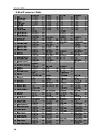
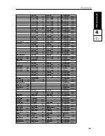
Page 157: ... Delay Time Mod Depth Mod Speed 25 Flanger 1 0 200 ms 5 0 99 50 1 99 20 26 Flanger 2 0 200 ms 24 0 99 99 1 99 42 27 Crossover Flanger 0 200 ms 1 0 99 60 1 99 22 Blend Emphatic Point 28 Exciter 99 99 60 1 10 1 Harmonic Density Hot Spot Stereo Width Delay Time 29 Enhancer 1 99 28 1 20 3 0 99 85 1 99 25 Drive Hot Spot Resonance EQ Low 30 Distortion 1 111 107 0 99 99 0 99 7 12 12 dB 0 31 Overdrive 1 1...

Page 158: ...ffect 67 33 Resonance EQ Low EQ High Dry Effect Mix 99 99 80 12 12 dB 0 12 12 dB 0 Dry Effect 50 50 99 99 36 12 12 dB 0 12 12 dB 0 Dry Effect 50 50 99 99 80 12 12 dB 0 12 12 dB 0 Dry Effect 50 50 EQ Low EQ High Dry Effect Mix 12 12 dB 3 12 12 dB 3 Dry Effect 50 50 EQ Low EQ High Dry Effect Mix 12 12 dB 0 12 12 dB 0 Dry Effect 50 50 EQ High Output Level Dry Effect Mix 12 12 dB 0 0 99 6 Dry Effect 5...

Page 159: ...ngs 0D Computer Select Sets PC I F clock 1A 1G Scale Type User Scale Sets the scale type and the user scale 1H 1I Sub Scale Sets the sub scale 2A Global MIDI Channel Specifies MIDI Global Channel and filters note data 2B External Out Select Selects MIDI OUT or TO HOST for data transmission 2C 2D MIDI Filter Transmission reception switches for MIDI messages 3A 3B Prog Protect Combi Protect Memory p...

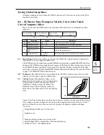
Page 160: ...n 0A Master Tune Tune 50 50 Used to tune the X5DR in cent steps 0B Transpose Trans 12 12 Used to transpose the X5DR in semitone steps 0C Velocity curve Vel 1 8 Velocity response curve After Touch curve Aft 1 8 After Touch response curve 0D Computer Select 31 25 kBPS 38 4 kBPS Baud rate setting for communication with a computer 00A MASTERTUNE ø Tune 00 440 00Hz 0A 0B 0C 00D PC I F CLK 31 25kBPS 0D ...

Page 161: ... Curve 7 changes in steps of 12 and allows the pitch to change in semitones when pitch shift width forAfter Touch is set to one octave Curve 8 is random You can use this when you wish to achieve a special effect or give an irregular pitch shift through After Touch After Touch Curve 1 Strong playing produces an obvious effect 2 3 Standard curve 4 5 Moderate playing produces an obvious effect 6 A li...

Page 162: ... that was used in the latter part of the baroque period Kirnberger Developed in the 18th Century used mainly for harpsichord Slendro Indonesian gamelan tuning with 5 notes per octave When key is set to C notes C D F G A are used Other notes are set to equal temperament Pelog Like the slendro scale but with 7 notes per octave When key is set to C notes C D E F G A B are used User Scale This allows ...

Page 163: ...d the sub 1G Copy Scale This is used to create your own scale based on one of the preset scales The scale selected here is copied to the user scale to enable you to edit it using pages 1C 1F 1H Sub Scale It is possible to switch between two scales main and sub using a pedal switch connected to a keyboard such as the X3 If MIDI message Bn 04 00 3F Controller 04 is set to 0 63 is received the main s...

Page 164: ...s should be set to ALL However if you want to increase the number of available notes by using another X5DR X5 or tone generator simultaneously feed data to both tone generators and set one to ODD and the other to EVEN LCD Parameter Range Description 2A Global MIDI Channel CH 1 16 Sets the Global MIDI Channel Note Receive Filter Note R EVEN ODD ALL Responds to even notes only Responds to odd notes ...

Page 165: ...asically the same as for ENA except that MIDI Bank Select messages are ignored The following table shows the Program Change and Bank Select receive conditions X Not received q Program Change received only O Program Change and Bank Select received With the ENA or PRG setting changing Programs in Program play mode will cause Program Change and Bank Select messages to be transmitted Changing Combinat...

Page 166: ... the X5DR receives MIDI Dump data 3C Page Memory The Page Memory function remembers the current LCD screen when you exit a mode The next time you enter that particular mode the same LCD screen is selected automatically In Multi mode however this function will not take you to the following parameter pages Damper Pedal Filter After Touch Filter Control Change Filter Key Window Bottom and Velocity Wi...

Page 167: ...r on OK then press the button to dump When transmission is completed Completed appears on the screen Press the or button to return to the previous screen The following table lists the data size and dump time for each Data Dump If Multi or All data is selected for data dump each data dump operation transmits dump data followed by Multi Setup Data exp and two types of data is sent to the data filer ...

Page 168: ... the transmit device is set to the Global MIDI Channel If you send data saved in the data filer set the Global MIDI Channel to the Global MIDI Channel on the transmit device that was selected when you saved the data See MIDI Data Format on page 163 Dump Data Compatibility Dump data is compatible between the X5DR and X5 although the following parameters are incompatible since the X5DR does not have...

Page 169: ...xternal Out Select MIDI MIDI Filter NUM for PRG DIS for EX ENA for others LCD Parameter Range Description 5A Preset Data Load Source ALL Combination CMB Program PRG Drum Kit KIT Select a preset data source to load Loads all data of Preset a or b Multi data and Global data Loads one Combination of Preset a or b Loads one Program of Preset a or b Loads one Drum Kit of Preset a or b Source ALL PER a ...

Page 170: ...to be loaded to Drum Kit 1 or 2 in the internal memory If memory protect is on for the Combinations Programs or Drum Kits you cannot load the corresponding data Turn memory protect off on page 3A and 3B Preset b data is the same as the sound data of X5 and 05R W When you load data using Source CMB Source PRG or Source KIT the X5DR may produce Program sound that is different from the sound of Progr...

Page 171: ...rum Sound this parameter allows you to select a drum sound for the currently selected index A setting of means that no drum sound is selected See Voice Name List for available drum sounds 6B Key this parameter allows you to select the note that will trigger the index It is not possible to select the same key for two indexes So if you want to select a key that is being used by another index set the...

Page 172: ...ering the closed hi hat Just like pressing a real hi hat pedal When SLF is selected the index will be monophonic In other words while a long drum sound such as a crash cymbal is playing if it is re triggered the drum sound plays again from the beginning 6D Pan This parameter is used to pan the index between buses A and B These buses feed the effects processors See 20A 20B Effect Placement on page ...

Page 173: ...exes are summarized 7A 7D Drum Kit2 Setup These parameters allow you to set up Drum kit2 Operation is the same as for 6A 6D Drum Kit1 Setup on page 158 8A Drum Kit Copy This function allows you to copy a drum kit to the internal Drum Kit 1 or 2 To copy a drum kit select the source and destination position the cursor on OK then press the button The message AreYou Sure OK will appear A1 Drum Kit1 A2...

Page 174: ...place the battery yourself Error Message Meaning Memory Protected The Program or Combination memory into which you are trying to write data is protected X5DR Tone Generation System AI2 Advanced Integrated Synthesis Tone Generator Single mode 64 voice 64 oscillators Double mode 32 voice 64 oscillators PCM Waveform Memory PCM 8MB Effects Two digital multi effects processors 47 effects Programs 236 1...

Page 175: ...DI data filters except Program for each track Key Window Bottom for each track Velocity Window Bottom for each track MIDI channel for each track In Global mode individual editing is possible only for drum kit parameters and for this type of editing you will use Drum Parameter Change messages The procedure is the same as for Parameter Change messages No 51 Global Data Dump parameters include some t...

Page 176: ... Panel 2 Select Add Tone generator section TO HOST THRU OUT IN Tone generator section TO HOST THRU OUT IN If the application sequencer etc being used supports Windows MME Multimedia Extensions the KORG MIDI Driver program provided as an accessory can be used to drive the X5DR connected to the serial port COM port as a MIDI device MIDI In data may not be received correctly if the processing speed o...

Page 177: ...iver program has been inserted in DriveA type A if the disk is in Drive B type B Then click on OK 5 Select Korg PC I F Driver and click on OK The setup screen appears Follow the instructions listed under Setting Up the KORG MIDI Driver Windows on page 165 6 To make the Driver effective eject the disk and select Restart ...

Page 178: ...the Independent Synth MIDI Out box is not checked data output to the MIDI Out port will be sent to both the tone generator of the X5DR and the MIDI Out port 4 The items listed under Synth Out Messages can be used to select messages to be sent to the X5DR The items listed under MIDI Out Messages can be used to select messages to be output from the MIDI Out port on the X5DR If the check mark in the ...

Page 179: ... is not used When the KORG MIDI Driver is used In order to use the KORG MIDI Driver the Apple MIDI Manager and PatchBay must be installed 1 Copy the KORG MIDI Driver on the accessory disk into the System Folder on the startup disk 2 If the Apple MIDI Driver is already in the System Folder either erase it or move it into another folder The KORG MIDI Driver includes the functions of the Apple MIDI D...

Page 180: ...en selected for the interface type 5 Pressing the Out Port Setting button displays the MIDI Channel dialog box In this box you can select the MIDI channels messages to be output to each of the ports Only channels messages which have been checked will be output 6 Drag the mouse from the arrow on the Out Port of the MIDI application sequencer etc and connect it to the Synth Out Port of the Korg MIDI...

Page 181: ...on 113 Drum Kit 160 Effects 119 Scale 150 Color Intensity 86 90 Color Velocity 86 90 Cursol iii 23 26 27 29 Cutoff 42 D Damper Pedal 1 Damper Pedal Filter Combination 104 Multi 111 Data Dump 74 154 Delay Start OSC2 82 Demo Song 3 15 Detune Combination 103 Multi 110 Program 82 Distortion Effect 49 132 DOUBLE OSC 45 79 Drum Kit 53 158 160 Index 158 Copy 160 Drum Program 17 22 68 DRUMS OSC 79 Drum So...

Page 182: ...LCD display iv Level Combination 101 Drum Kit 159 Multi 109 OSC 80 82 LSB 71 M Main Scale 61 Master Balance 73 Master Tune 71 147 Master Volume 73 Memory Protect 153 MG 37 MIDI 28 30 32 65 MIDI Controller Filter 151 MIDI Connectors 30 65 MIDI Channel Global 31 151 Combination 31 102 Multi 17 32 113 Program 2 21 31 MIDI Data Format 163 MIDI Filter 75 Global 151 Combination 104 Multi 111 MIDI Implem...

Page 183: ...Sub Scale 69 149 Type 149 User Scale 149 Send C D 45 70 Combination 105 Drum Kit 159 Multi 109 Program 81 82 Serial Placement 118 SINGLE OSC 79 Specifications 161 Stereo Delay Effect 48 123 Split 25 61 Symphonic Ensemble Effect 129 T Timber 7 24 31 TO HOST 12 13 30 Track 16 27 32 107 Transpose Combination 103 Global 147 Multi 110 Tremolo Effect 49 135 Troubleshooting 57 Tune 54 159 Tuning 60 147 U...

Reviews: