


6. Product Description
KISS 4U KTC5520 – User's Guide (Version 1.01)
6.1.2.
Power Button
The power button (see Fig. 11, pos. 14 and Fig. 12, pos. 1) is located on the front side of the system, behind the front
access panel. Press this button to turn the system on or off. Please observe the setting options for the power button in the
BIOS-Setup.
Even when the system is turned off via the power button there is still a standby-voltage of 5 VSb on the
server board.
The unit is only completely disconnected from the mains, when the ON/OFF switch of the AC power
supply unit is set to OFF or when the power cord is disconnected either from the mains or the unit.
Therefore, the power cord and its connectors must always remain easily accessible.
6.1.3.
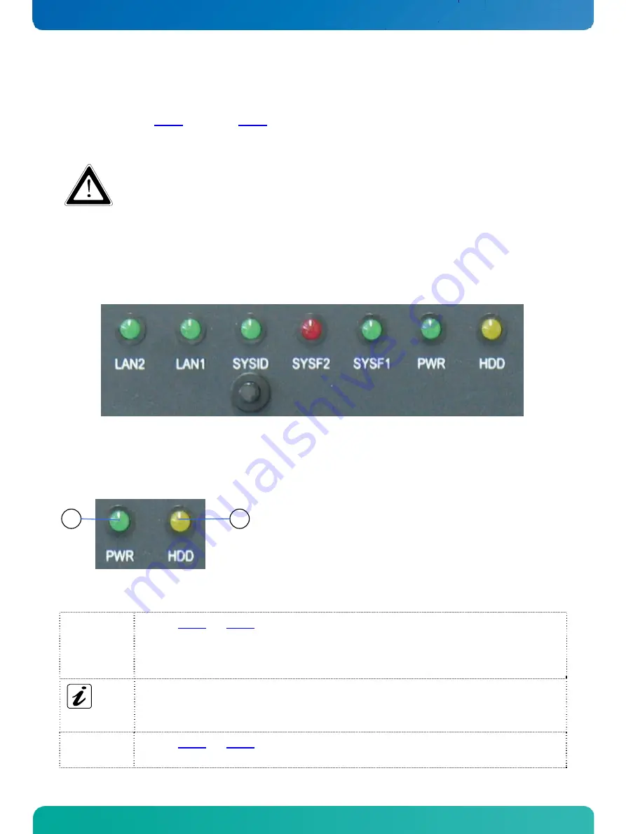
LED Indicators and the SYSID Button
Fig. 13: LED indicators ans SYSID button on the front side
6.1.3.1.
Power- and HDD-LED
The Power LED marked “PWR” and the hard disk LED marked “HDD” of the KISS 4U KTC5520 platform are located on the
front side, behind the front access door.
2
1
1
Power LED
2
HDD activity LED
Fig. 14: Power and HDD LED on the front side
Power LED
(green)
This LED (Fig. 13 and Fig. 14, pos. 1) lights up green when the system is turned on via the power
switch of the PSU and the power button.
Prerequisite:
The system has to be connected to an appropriate AC main power supply.
Please observe the option in BIOS Setup / Advanced / Chipset Configuration / South Bridge
Configuration / Restore on AC Power Loss with the option settings:
Power Off /
Power On/ /Last State.
The KISS 4U KTC5520 platform is delivered with the default setting “Power Off”.
HDD LED
(yellow)
This LED (Fig. 13 and Fig. 14, pos. 2) lights up during hard disk activity.
16
www.kontron.com