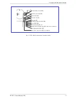


9. Jumpers and Connectors Overview
PCI-760 – User’s Manual (V1.00)
23
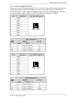
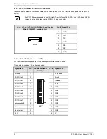
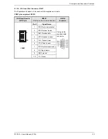
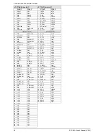
Hard Disk Drive LED: pins 15 and 16
To these pins can be connected a hard drive activity LED. This LED will flash when the HDD is being accessed.
Speaker:-pins 7 and 8
These-pins provide an interface to connect a speaker for audio tone generation. An 8-ohm speaker is recommended.
Keyboard:-pins 1, 2, 3, and 5
These-pins can be used to connect the cable connection for an external
PS/2 keyboard connector.
Mouse:-pins 9, 10, 11, and 5
These-pins can be used to connect the cable connection for an external
PS/2 mouse connector.
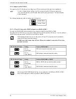
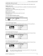
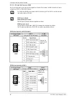
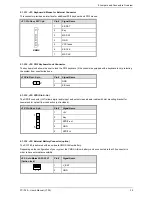
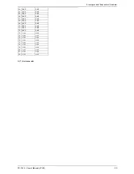
9.1.3.3.
J34: Additional Power Button Connector
This connection allows you to attach an external ATX power button.
J34: 2-pin Row
Pin #
Signal Name
1
2
1 GND
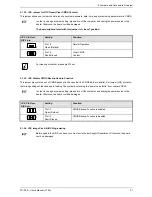
9.1.3.4.
J1: CPU Fan Power Connector
It is a 4-pin header that allows the connection of the CPU fan. The CPU fan must be a 12V fan (max. 750 mA).
J1: 4-pin Molex Connector (friction lock)
Pin # Signal Name
1 CTRL
(PWM)
2 Rotation
3 +12V
1
4
4 GND
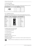
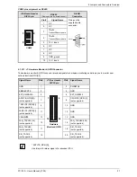
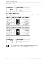
9.1.3.5.
J4: Chassis Fan1 Power Connector
It is a 4-pin header that allows the connection of a chassis fan. The chassis fan must be a 12V fan (max. 750 mA).
J4:- 4-pin Molex Connector (friction lock) Pin # Signal Name
1 CTRL
(PWM)
2 Rotation
3 +12V
1
4
4 GND
9.1.3.6.
J24: Chassis Fan2 Power Connector
It is a 4-pin header that allows the connection of a chassis fan. The chassis fan must be a 12V fan (max. 750 mA).
J24: 4-pin Molex Connector (friction lock) Pin # Signal Name
1 CTRL
(PWM)
2 Rotation
3 +12V
1
4
4 GND
Also a 3-pin FAN connector cable can be can be connected to each of J1, J4 or J24. In this case the
corresponding fan is operating with full speed.


