background image

2 8

G e n e r a l i d a d e s

28.1 Sobre este manual . . . . . . . . . . . . . . . . . . . . . . . . . . . . . . . . . . . . . . . . . . . . . . . . . . . . . . . . . . . . . .57
28.2 Símbolos utilizados. . . . . . . . . . . . . . . . . . . . . . . . . . . . . . . . . . . . . . . . . . . . . . . . . . . . . . . . . . . . . .57
28.3 Abreviaturas utilizadas . . . . . . . . . . . . . . . . . . . . . . . . . . . . . . . . . . . . . . . . . . . . . . . . . . . . . . . . . . .57

2 9

S e g u r i d a d

29.1 Siga sus instrucciones!. . . . . . . . . . . . . . . . . . . . . . . . . . . . . . . . . . . . . . . . . . . . . . . . . . . . . . . . . . .58
29.2 Utilización conforme . . . . . . . . . . . . . . . . . . . . . . . . . . . . . . . . . . . . . . . . . . . . . . . . . . . . . . . . . . . . .59
29.3 Uso indebido. . . . . . . . . . . . . . . . . . . . . . . . . . . . . . . . . . . . . . . . . . . . . . . . . . . . . . . . . . . . . . . . . . .59

3 0

M a n i p u l a c i ó n

30.1 Transporte . . . . . . . . . . . . . . . . . . . . . . . . . . . . . . . . . . . . . . . . . . . . . . . . . . . . . . . . . . . . . . . . . . . .60
30.2 Embalaje. . . . . . . . . . . . . . . . . . . . . . . . . . . . . . . . . . . . . . . . . . . . . . . . . . . . . . . . . . . . . . . . . . . . . .60
30.3 Almacenamiento . . . . . . . . . . . . . . . . . . . . . . . . . . . . . . . . . . . . . . . . . . . . . . . . . . . . . . . . . . . . . . . .60
30.4 Advertenzia / Limpieza . . . . . . . . . . . . . . . . . . . . . . . . . . . . . . . . . . . . . . . . . . . . . . . . . . . . . . . . . . .60
30.5 Reparación . . . . . . . . . . . . . . . . . . . . . . . . . . . . . . . . . . . . . . . . . . . . . . . . . . . . . . . . . . . . . . . . . . . .60
30.6 Eliminación . . . . . . . . . . . . . . . . . . . . . . . . . . . . . . . . . . . . . . . . . . . . . . . . . . . . . . . . . . . . . . . . . . . .60

3 1

I d e n t i f i c a c i ó n d e l p r o d u c t o

31.1 Volumen de suministro . . . . . . . . . . . . . . . . . . . . . . . . . . . . . . . . . . . . . . . . . . . . . . . . . . . . . . . . . . .61
31.2 Placa de identificación . . . . . . . . . . . . . . . . . . . . . . . . . . . . . . . . . . . . . . . . . . . . . . . . . . . . . . . . . . .61
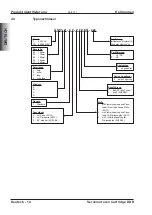
31.3 Codificación de modelo . . . . . . . . . . . . . . . . . . . . . . . . . . . . . . . . . . . . . . . . . . . . . . . . . . . . . . . . . .62

3 2

D e s c r i p c i ó n t é c n i c a

32.1 Datos técnicos generales . . . . . . . . . . . . . . . . . . . . . . . . . . . . . . . . . . . . . . . . . . . . . . . . . . . . . . . . .63

32.1.1

Forma de diseño . . . . . . . . . . . . . . . . . . . . . . . . . . . . . . . . . . . . . . . . . . . . . . . . . . . . . . . . . . .63

32.1.2

Brida . . . . . . . . . . . . . . . . . . . . . . . . . . . . . . . . . . . . . . . . . . . . . . . . . . . . . . . . . . . . . . . . . . . .63

32.1.3

Tipo de protección . . . . . . . . . . . . . . . . . . . . . . . . . . . . . . . . . . . . . . . . . . . . . . . . . . . . . . . . . .64

32.1.4

Clase de material aislante . . . . . . . . . . . . . . . . . . . . . . . . . . . . . . . . . . . . . . . . . . . . . . . . . . . .64

32.1.5

Superficie. . . . . . . . . . . . . . . . . . . . . . . . . . . . . . . . . . . . . . . . . . . . . . . . . . . . . . . . . . . . . . . . .64

32.1.6

Dispositivo protector . . . . . . . . . . . . . . . . . . . . . . . . . . . . . . . . . . . . . . . . . . . . . . . . . . . . . . . .64

32.1.7

Sistema de conexión . . . . . . . . . . . . . . . . . . . . . . . . . . . . . . . . . . . . . . . . . . . . . . . . . . . . . . . .64

32.1.8

Unidad de realimentación (Feedback) . . . . . . . . . . . . . . . . . . . . . . . . . . . . . . . . . . . . . . . . . .64

3 3

I n s t a l a c i ó n m e c á n i c a

33.1 Instrucciones importantes . . . . . . . . . . . . . . . . . . . . . . . . . . . . . . . . . . . . . . . . . . . . . . . . . . . . . . . .65
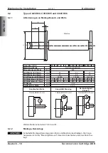
33.2 Tipos C04/CH04, C05/CH05 y C06/CH06 . . . . . . . . . . . . . . . . . . . . . . . . . . . . . . . . . . . . . . . . . . . .66

33.2.1

Requisitos de la brida de montaje y el eje . . . . . . . . . . . . . . . . . . . . . . . . . . . . . . . . . . . . . . .66

33.2.2

Montaje, Desmontaje . . . . . . . . . . . . . . . . . . . . . . . . . . . . . . . . . . . . . . . . . . . . . . . . . . . . . . .66

33.3 Tipos C09/CH09 y C13/CH13 . . . . . . . . . . . . . . . . . . . . . . . . . . . . . . . . . . . . . . . . . . . . . . . . . . . . .67

33.3.1

Requisitos de la brida de montaje y el eje . . . . . . . . . . . . . . . . . . . . . . . . . . . . . . . . . . . . . . .67

33.3.2

Montaje, Desmontaje . . . . . . . . . . . . . . . . . . . . . . . . . . . . . . . . . . . . . . . . . . . . . . . . . . . . . . .67

3 4

I n s t a l a c i ó n e l é c t r i c a

34.1 Instrucciones importantes. . . . . . . . . . . . . . . . . . . . . . . . . . . . . . . . . . . . . . . . . . . . . . . . . . . . . . . . .68
34.2 Conexión de los motores con conducciones preconfeccionadas . . . . . . . . . . . . . . . . . . . . . . . . . . 68
34.3 Guía de instalación eléctrica . . . . . . . . . . . . . . . . . . . . . . . . . . . . . . . . . . . . . . . . . . . . . . . . . . . . . .69

3 5

P u e s t a e n f u n c i o n a m e n t o

35.1 Instrucciones importantes. . . . . . . . . . . . . . . . . . . . . . . . . . . . . . . . . . . . . . . . . . . . . . . . . . . . . . . . .70
35.2 Guía de puesta en funcionamento . . . . . . . . . . . . . . . . . . . . . . . . . . . . . . . . . . . . . . . . . . . . . . . . . .70
35.3 Eliminación de perturbaciones . . . . . . . . . . . . . . . . . . . . . . . . . . . . . . . . . . . . . . . . . . . . . . . . . . . . .71

3 6

D a t o s t é c n i c o s

36.1 Definiciones . . . . . . . . . . . . . . . . . . . . . . . . . . . . . . . . . . . . . . . . . . . . . . . . . . . . . . . . . . . . . . . . . . .72

Español - 6

Servomotores Cartridge DDR

Sumario

04/2017

Kollmorgen

P á g i n a

ESPAÑOL

Summary of Contents for C04/CH04 Series

Page 1: ...eil während der Lebensdauer des Produktes auf Geben Sie das Handbuch an nachfolgende Benutzer oder Besitzer des Produktes weiter Keep the manual as a product component during the life span of the product Pass the manual to future users owners of the product Conservare il manuale per l intera durata del prodotto In caso di cambio di proprietà il manuale deve essere fornito al nuovo uti lizzatore qu...

Page 2: ...printed in the Federal Republic of Germany All rights reserved No part of this work may be reproduced in any form by printing photocopying microfilm or any other method or stored processed copied or distributed by electronic means without the written per mission of Kollmorgen Europe GmbH Il produttore si riserva la facoltà di apportare modifiche tecniche volte al miglioramento degli appa recchi Tr...

Page 3: ...erfläche 16 5 1 6 Schutzeinrichtung 16 5 1 7 Anschlusstechnik 16 5 1 8 Rückführeinheit 16 6 Mechanische Installation 6 1 Wichtige Hinweise 17 6 2 Typen C04 CH04 C05 CH05 und C06 CH06 18 6 2 1 Anforderungen an Montageflansch und Welle 18 6 2 2 Montage Demontage 18 6 3 Typen C09 CH09 und C13 CH13 19 6 3 1 Anforderungen an Montageflansch und Welle 19 6 3 2 Montage Demontage 19 7 Elektrische Installat...

Page 4: ...class 32 14 1 5 Surface 32 14 1 6 Protective device 32 14 1 7 Connection method 32 14 1 8 Feedback 32 15 Mechanical Installation 15 1 Important Notes 33 15 2 Types C04 CH04 C05 CH05 and C06 CH06 34 15 2 1 Mounting flange and shaft requirements 34 15 2 2 Mounting Removal 34 15 3 Types C09 CH09 and C13 CH13 35 15 3 1 Mounting flange and shaft requirements 35 15 3 2 Mounting Removal 35 16 Electrical ...

Page 5: ...solamento 48 23 1 5 Superficie 48 23 1 6 Dispositivo di protezione 48 23 1 7 Sistema di collegamento 48 23 1 8 Unità di retroazione 48 24 Installazione meccanica 24 1 Indicazioni importanti 49 24 2 Modelli C04 CH04 C05 CH05 e C06 CH06 50 24 2 1 Requisiti per flangia di montaggio e albero 50 24 2 2 Montaggio Smontaggio 50 24 3 Modelli C09 CH09 e C13 CH13 51 24 3 1 Requisiti per flangia di montaggio...

Page 6: ...uperficie 64 32 1 6 Dispositivo protector 64 32 1 7 Sistema de conexión 64 32 1 8 Unidad de realimentación Feedback 64 33 Instalación mecánica 33 1 Instrucciones importantes 65 33 2 Tipos C04 CH04 C05 CH05 y C06 CH06 66 33 2 1 Requisitos de la brida de montaje y el eje 66 33 2 2 Montaje Desmontaje 66 33 3 Tipos C09 CH09 y C13 CH13 67 33 3 1 Requisitos de la brida de montaje y el eje 67 33 3 2 Mont...

Page 7: ...8 Dimension drawings 38 1 Dimensions C04 CH04 79 38 2 Dimensions C05 CH05 80 38 3 Dimensions C06 CH06 81 38 4 Dimensions C09 CH09 82 38 5 Dimensions C13 CH13 83 39 Wiring diagram Motor Encoder 40 Approvals 40 1 Conformance with UL 85 40 2 Conformance with CE 85 40 3 Conformance with RoHS 85 40 4 Conformance with REACH 85 40 5 EAC Conformance 85 Servomotores Cartridge DDR Español 7 Kollmorgen 04 20...

Page 8: ...Diese Seite wurde bewusst leer gelassen Deutsch 8 Servomotoren Cartridge DDR 04 2017 Kollmorgen DEUTSCH ...

Page 9: ...auf eine gefährliche Situation hin die wenn sie nicht ver mieden wird zum Tode oder zu schweren irreversiblen Verlet zungen führen wird WARNUNG Weist auf eine gefährliche Situation hin die wenn sie nicht ver mieden wird zum Tode oder zu schweren irreversiblen Verlet zungen führen kann VORSICHT Weist auf eine gefährliche Situation hin die wenn sie nicht ver mieden wird zu leichten Verletzungen führ...

Page 10: ...iten am Motor betrauten Personen das Pro dukthandbuch gelesen und verstanden haben l Heben und bewegen Sie Motoren mit mehr als 20kg Gewicht nur mit Hilfe von He bevorrichtungen Heben ohne Hilfsmittel kann zu Rückenverletzungen führen Hohe Spannungen Stellen Sie die ordnungsgemäße Erdung des Motorgehäuses mit der PE Schiene im Schaltschrank als Bezugspotential sicher Gefahr durch elektrischen Schl...

Page 11: ...rden l Der in die Motorwicklungen eingebaute Temperatursensor muss ausgewertet und überwacht werden l Die Konformität des Servosystems zu den in der EG Konformitätserklärung siehe Kollmorgen Website genannten Normen garantieren wir nur wenn von uns gelie ferte Komponenten Servoverstärker Motor Leitungen usw verwendet werden 2 3 Nicht bestimmungsgemäße Verwendung l Der Betrieb der Motoren in folgen...

Page 12: ...3 3 Lagerung l Lagertemperatur 25 55 C max 20K Stunde schwankend l Luftfeuchtigkeit relative Feuchte 5 95 nicht kondensierend l Nur in der recyclebaren Originalverpackung des Herstellers lagern l Max Stapelhöhe siehe Tabelle Verpackung l Lagerdauer ohne Einschränkung 3 4 Wartung Reinigung l Wartung und Reinigung nur von qualifiziertem Personal l Öffnen der Motoren bedeutet den Verlust der Gewährle...

Page 13: ... Stillstandsstrom STALL PEAK Ipeak Spitzenstrom VOLTS Nennspannung MAX SPEED Spitzendrehzahl CLASS Isolierstoffklasse Temperatur FREQ Netzfrequenz KB Spannungskonstante RES L L 25 C Wicklungswiderstand bei 25 C Das Baujahr des Motors ist in der Seriennummer kodiert die ersten beiden Ziffern der Seriennummer bezeichen das Jahr z B 12 bedeutet 2012 Servomotoren Cartridge DDR Deutsch 13 Kollmorgen 04...

Page 14: ... extra lang Option Kugellager 0 keine Lagerung Abdichtung 5 abgedichtet Zertifizierung _ UL CE S CE Ausführung fortlaufende Nummer für Sonderausführungen Flansch 1 Standard Anschlüsse 1 zur Seite 09 13 2 zur Rückseite 09 13 3 90 drehbar 04 05 06 Rückführung 1 EnDAT alle Typen 3 BiSS 04 05 06 Welle 1 mit Klemmkupplung und Pass feder für durchgehende Welle 09 13 2 mit Klemmkupplung und Pass feder fü...

Page 15: ...eduzierung um 10K 1000m Technische Daten für die Motoren finden Sie in Kapitel Technical Data ab S 73 5 1 1 Bauform Der Motor kann in beliebiger Einbaulage also auch an horizontalen oder vertikalen Wel len montiert werden 5 1 2 Flansch Die Cartridge DDR besitzen keinen eignen Flansch sondern werden mit einer Klemm kupplung und Zentrierring an den Maschinenflansch montiert Ein Passring am Motor die...

Page 16: ...r PTC ist bei Verwendung unserer vorkonfektionierten Encoder leitung in das Überwachungssystem der digitalen Servoverstärker integriert 5 1 7 Anschlusstechnik Die Motoren sind mit Steckern für die Leistungsversorgung und die Encodersignale aus gerüstet Die Stecker weisen je nach Ausführung entweder zur Seite oder zur Rückseite des Motors oder sind um 90 drehbar Die Gegenstecker gehören nicht zum L...

Page 17: ...icht montiert ist um Verschmutzung zu verhindern l Schützen Sie die Motoren vor unzulässiger Beanspruchung Insbesondere dürfen bei Transport und Handhabung keine Bauelemente verbogen und oder Isolationsabstände verändert werden l Der Einbauort muss frei von leitfähigen und aggressiven Stoffen sein Bei gekapseltem Einbau sollten Sie zunächst mit unserer Applikationsabteilung Rüc ksprache nehmen l M...

Page 18: ... 117 E Wellenlänge 1 5mm mm 61 3 92 3 123 3 154 3 82 107 132 157 104 138 172 F Rezess mm 5 5 Axialspiel der Welle mm 0 13 Rundlauf der Welle Koaxialität Passring Rechtwinkligkeit Flansch Toleranzfeld 0 13 mm Toleranzfeld 0 10 mm Toleranzfeld 0 10 mm Weitere Maße siehe Seiten 79 80 und 81 6 2 2 Montage Demontage Fehlerhafte Montage Demontage kann Motor und Maschine beschädigen Die Vorge hensweise i...

Page 19: ... 1 5mm mm 89 92 134 11 170 69 114 05 167 89 253 49 F Rezess mm 13 5 17 8 Axialspiel der Welle mm statisch 1 5 dynamisch 0 05 Rundlauf der Welle Koaxialität Passring Rechtwinkligkeit Flansch Toleranzfeld 0 038 mm Toleranzfeld 0 051 mm Toleranzfeld 0 051 mm Weitere Maße siehe Seiten 82 und 83 6 3 2 Montage Demontage Fehlerhafte Montage Demontage kann Motor und Maschine beschädigen Die Vorge hensweis...

Page 20: ... Spannung im Zwischenkreis und warten Sie bis die Spannung unter 50V abgesunken ist Das Masse Zeichen X das Sie in allen Anschlussplänen finden deutet an dass Sie für eine möglichst großflächige elektrisch leitende Verbindung zwischen dem gekenn zeichneten Gerät und der Montageplatte in Ihrem Schaltschrank sorgen müssen Diese Verbindung soll die Ableitung von HF Störungen ermöglichen und ist nicht...

Page 21: ...ung geschaltet werden siehe Betriebsanleitung des Servoverstärkers und Zubehörhandbuch l Achten Sie auf einwandfreie Erdung von Servoverstärker und Motor EMV gerechte Abschirmung und Erdung siehe Betriebsanleitung des verwendeten Servoverstär kers Erden Sie Montageplatte und Motorgehäuse l Verdrahtung Leistungs und Steuerkabel möglichst getrennt verlegen Encoder anschließen Motorleitungen anschlie...

Page 22: ...ist nicht auszuschließen dass der Antrieb ungeplant eine Bewegung durchführt Stellen Sie sicher dass auch bei ungewollter Bewegung des Antriebs keine Gefährdung von Personen oder Sachen eintreten kann Die Maßnahmen die Sie dazu in Ihrer Anwendung treffen müssen ergeben sich aus der Risikobeurteilung der Anwendung 8 2 Leitfaden für die Inbetriebnahme Das Vorgehen bei der Inbetriebnahme wird exempla...

Page 23: ...st mechanisch blockiert ENABLE Signal anlegen Sollwertleitung prüfen Motorphasen korrekt auflegen Mechanik prüfen Motor geht durch Motorphasen vertauscht Motorphasen korrekt auflegen Motor schwingt Abschirmung Encoderleitung unterbrochen Verstärkung zu groß Encoderleitung erneuern Motordefaultwerte verwenden Fehlermeldung Endstufenfehler Motorleitung hat einen Kurz oder Erdschluss Motor hat einen ...

Page 24: ...dem 3 fachen Stillstandsstrom Der Spitzenstrom des verwendeten Servoverstärkers muss kleiner sein Drehmomentkonstante KTrms Nm A Die Drehmomentkonstante gibt an wie viel Drehmoment in Nm der Motor mit 1A Sinus Effektivstrom erzeugt Es gilt M I x KT bis maximal I 2 x I0 Spannungskonstante KErms mVmin Die Spannungskonstante gibt die auf 1000U min bezogene induzierte Motor EMK als Sinus Effektivwert ...

Page 25: ...t WIKI available at www wiki kollmorgen eu 10 2 Symbols used Symbol Indication DANGER Indicates a hazardous situation which if not avoided will result in death or serious injury WARNING Indicates a hazardous situation which if not avoided could result in death or serious injury CAUTION Indicates a hazardous situation which if not avoided could result in minor or moderate injury This is not a safet...

Page 26: ... understood the manual and that the safety notices in this ma nual are observed l Lift and move motors with more than 20kg weight only with lifting tools Lifting unas sisted could result in back injury High voltages It is vital that you ensure that the motor housing is safely earthed to the PE protective earth busbar in the switch cabinet Risk of electric shock Electrical safety is impossible with...

Page 27: ...s or machines l The thermal sensor which is integrated in the motor windings must be observed and evaluated l The conformity of the servo system to the standards mentioned in the EC Declarati on of Conformity see Kollmorgen Website only guaranteed when the components servo amplifier motor cables etc that are used have been supplied by us 11 3 Prohibited use l The use of the motors in the following...

Page 28: ...e temperature 25 55 C max variation 20K hr l Humidity rel humidity 5 95 no condensation l Store only in the manufacturer s original recyclable packaging l Max stacking height see table under Packaging l Storage time unlimited 12 4 Maintenance Cleaning l Maintenance and cleaning only by qualified personnel l Opening the motor invalidates the warranty l If the housing is dirty clean housing with Iso...

Page 29: ...ak peak current VOLTS Rated voltage MAX SPEED Maximum speed CLASS Insulation class temperatur class FREQ Mains frequency KB Voltage constant RES L L 25 C Winding resistance 25 C Year of manufacturing is coded in the serial number the first two digits of the serial num ber are the year of manufacturing e g 12 means 2012 Servomotors Cartridge DDR English 29 Kollmorgen 04 2017 Package ENGLISH ...

Page 30: ... 2 medium 3 long 4 extra long Option Bearing 0 no bearing Sealing 5 sealed Certificates _ UL CE S no UL Specials Numbers for customer specials Flange 1 Standard Connections 1 sidewards 09 13 2 backwards 09 13 3 90 rotatable 04 05 06 Feedback 1 EnDAT all types 3 BiSS 04 05 06 Shaft 1 with compression coupling and key for pass through shaft 09 13 2 with compression coupling and key for shaft 09 13 3...

Page 31: ...000m Technical motor data can be found in chapter Technical Data from p 73 14 1 1 Design The motor can be installed in any mounting position including mounting on horizontal or vertical shafts 14 1 2 Flange The Cartridge DDR do not have their own flange instead they are mounted to the machine flange using a compression coupling and centring ring An adapter ring on the motor is used for centring on...

Page 32: ...avy overloading Provided that our preassembled Encoder cable is used the PTC is integra ted into the monitoring system of the digital servo amplifiers 14 1 7 Connection method The motors are equipped with connectors for the power supply and encoder signals Depending on the version the connectors are allocated to either the side or rear of the motor or they can be rotated by 90 The mating connector...

Page 33: ...material If the motor is not mounted this end of the motor must be covered to insure proper cleanliness l Protect the motor from unacceptable stresses Take care especially during transport and handling that components are not bent and that insulation clearances are not altered l The site must be free of conductive and aggressive material If an encapsulated as sembly is required please consult our ...

Page 34: ...9 110 35 60 85 110 49 83 117 E Shaft length 1 5mm mm 61 3 92 3 123 3 154 3 82 107 132 157 104 138 172 F Recess mm 5 5 Axial shaft movement mm 0 13 Shaft radial runout Pilot concentricity Flange perpendicularity 0 13 mm TIR 0 10 mm TIR 0 10 mm TIR More dimensions see pages 79 80 and 81 15 2 2 Mounting Removal Improper mounting may damage the motor and machine The procedure is described in the Mount...

Page 35: ...2 118 62 E Shaft length 1 5mm mm 89 92 134 11 170 69 114 05 167 89 253 49 F Recess mm 13 5 17 8 Axial shaft movement mm static 1 5 dynamic 0 05 Shaft radial runout Pilot concentricity Flange perpendicularity 0 038 mm TIR 0 051 mm TIR 0 051 mm TIR More dimensions see pages 82 and 83 15 3 2 Mounting Removal Improper mounting may damage the motor and machine The procedure is described in the Mounting...

Page 36: ...r leads may be live Measure the DC link voltage and wait until it has fallen below 50V The ground symbol X which you will find in the wiring diagrams indicates that you must provide an electrical connection with as large a surface area as possible between the unit indicated and the mounting plate in the switch cabinet This connection is to sup press HF interference and must not be confused with th...

Page 37: ...ructions manual of the servo amplifier and accessory manual l Ensure that there is proper earthing of the servo amplifier and the motor Use correct earthing and EMC shielding according to the instructions manual of the servo ampli fier which is used Earth the mounting plate and motor casing l Cabling Route power cables as separately as possible from control cables Connect up the Encoder Connect th...

Page 38: ...erforming unplanned movements during commissioning cannot be ruled out Make sure that even if the drive starts to move unintentionally no danger can result for personnel or machinery The measures you must take in this regard for your task are based on the risk assessment of the application 17 2 Guide for setup The procedure for setup is described as an example A different method may be appro priat...

Page 39: ... lead Motor phases in wrong sequence Drive is mechanically blocked Supply ENABLE signal Check setpoint lead Correct the phase sequence Check mechanism Motor runs away Motor phases in wrong sequence Correct the phase sequence Motor oscillates Break in the shielding of the Encoder cable amplifier gain to high Replace Encoder cable use motor default values Error message output stage fault Motor cable...

Page 40: ...the rated current The actual value is determined by the peak current of the servo amplifier which is used Torque constant KTrms Nm A The torque constant defines how much torque in Nm is produced by the motor with 1A r m s current The relationship is M I x KT up to I 2 x I0 Voltage constant KErms mV min 1 The voltage constant defines the induced motor EMF as an effective sinusoidal value between tw...

Page 41: ...i utilizzati Symbolo Significato PERICOLO Segnala una situazione di pericolo che se non evitata comporta la morte o lesioni gravi e permanenti AVVERTENZA Segnala una situazione di pericolo che se non evitata può comportare la morte o lesioni gravi e permanenti ATTENZIONE Segnala una situazione di pericolo che se non evitata può comportare infortuni leggeri Questo non è un simbolo di sicurezza Segn...

Page 42: ...o rispettate l Sollevare e spostare motori con un peso superiore ai 20 kg solo con l ausilio di op portuni dispositivi di sollevamento Sollevare i motori senza dispositivi ausiliari può causare lesioni alla schiena Alta tensione Assicurare la regolare messa a terra della carcassa del motore con la bandella PE all in terno dell armadio di distribuzione come potenziale di riferimento Pericolo di sco...

Page 43: ...iedono l analisi e il monitoraggio del termocontatto di protezione montato negli avvolgimenti del motore l Garantiamo la conformità del servosistema alle norme menzionate nella EC Decla ration of Conformity vedi Kollmorgen Website solo se vengono utilizzati componen ti originali servoamplificatori motore cavi e così via 20 3 Uso conforme vietato l È vietato l uso del motor nei seguenti ambienti ar...

Page 44: ...21 3 Stoccaggio l Temperatura di stoccaggio da 25 a 55 C variazione max 20K ora l Umidità atmosferica um rel del 5 95 senza condensa l Solo in imballaggio originale riciclabile del produttore l Per l altezza d impilaggio max ved tabella imballaggio l Durata a magazzino illimitata 21 4 Manutenzione Puliza l Solo da parte di personale qualificato l L apertura dei motori comporta l annullamento della...

Page 45: ...o STALL PEAK Ipeak corrente di picco VOLTS Tensione nominale MAX SPEED Velocità di picco CLASS Classe di isolamento temperatura FREQ Frequenza di rete KB Costante di tensione RES L L 25 C Resistenza avvolgimento a 25 C L anno di fabbricazione è codificato nel numero di serie le prime due cifre del numero di serie sono l anno di fabbricazione per esempio 12 significa 2012 Servomotori Cartridge DDR ...

Page 46: ...extra lang Cuscinetti a sfera opzionali 0 nessun cuscinetto Tenuta 5 chiusura a tenuta Certificazione _ UL CE S CE Versione numerazione continua per versioni speciali Flangia 1 Standard Collegamenti 1 sul lato 09 13 2 sul retro 09 13 3 ruotabili di 90 04 05 06 Retroazione 1 EnDAT tutti tipi 3 BiSS 04 05 06 Albero 1 con innesto di serraggio e chiavetta per albero passante 09 13 2 con innesto di ser...

Page 47: ... sopra il LdM e riduzione della temp di 10K 1000m Per i dati tecnici di ogni tipo di motore consultare il capitolo Technical Data da p 73 23 1 1 Forma costructtiva Il montaggio del motore può avvenire in qualsiasi posizione quindi anche su alberi oriz zontali o verticali 23 1 2 Flangia I motori Cartridge DDR non dispongono di flangia propria vengono invece montati sulla flangia della macchina con ...

Page 48: ... brevi molto elevati Utilizzando il nostro cavo per Encoder preconfezionato il PTC è integrato nel sistema di controllo dei servoamplificatori digitali 23 1 7 Sistema di collegamento I motori sono dotati di connettori diritti per l alimentazione di potenza e i segnali dell encoder A seconda della versione i connettori sono orientati sul lato o sul retro del motore oppure sono ruotabili di 90 Le pr...

Page 49: ...e attira il ferro Coprire l estremità del motore per evita re che si sporchi l Proteggere i motori da sollecitazioni non ammesse In particolare durante il trasporto e la movimentazione non piegare elementi costrut tivi e o modificare le distanze d isolamento l Il luogo di installazione deve essere privo di materiali conduttivi e aggressivi In caso di montaggio in esecuzione chiusa consultare prima...

Page 50: ...a albero 1 5mm mm 61 3 92 3 123 3 154 3 82 107 132 157 104 138 172 F Arretramento mm 5 5 Gioco assiale dell albero mm 0 13 Concentricità dell albero Coassialità anello adattatore Ortogonalità flangia 0 13 mm Campo di tolleranza 0 10 mm Campo di tolleranza 0 10 mm Campo di tolleranza Per le altre dimensioni vedere le pagine 79 80 e 81 24 2 2 Montaggio Smontaggio Un montaggio errato può danneggiare ...

Page 51: ...89 92 134 11 170 69 114 05 167 89 253 49 F arretramento mm 13 5 17 8 Gioco assiale dell albero mm statico 1 5 dinamico 0 05 Concentricità dell albero Coassialità anello adat tatore Ortogonalità flangia 0 038 mm Campo di tolleranza 0 051 mm Campo di tolleranza 0 051 mm Campo di tolleranza Per le altre dimensioni vedere le pagine 82 e 83 24 3 2 Montaggio Smontaggio Un montaggio errato può danneggiar...

Page 52: ...e fermo Misurare la tensione nel circuito intermedio e attendere fino a quando il valore è sceso al di sotto dei 50V Il simbolo messa a terra Xche si trova in tutti gli schemi di collegamento indica che occorre provvedere ad un collegamento conduttivo il più ampio possibile tra l apparecchio identificato e la piastra di montaggio nel quadro elettrico ad armadio Tale collegamento deve consentire la...

Page 53: ...icatore e motore venga eseguita a re gola d arte Per una schermatura e una messa a terra conformi ai requisiti di compa tibilità elettromagnetica si vedano le manuale del servoamplificatore utilizzato Colle gare a terra la piastra di montaggio e la carcassa del motore l Cablaggio Se possibile posare separatamente i cavi di potenza e di comando Collegare l unità di retroazione Collegare i cavi del ...

Page 54: ...nto imprevisto dell azionamento Assicurarsi che qualsiasi movimento accidentale dell azionamento non possa causare pericolo per persone o cose Le misure necessarie in questo caso per un applicazione specifica possono essere desunte dall analisi dei rischi dell applicazione 26 2 Guida ad messa in funzione A titolo di esempio descriviamo la procedura da seguire per la messa in funzione A seconda del...

Page 55: ...ore fuorigiri Fasi motore scambiate Impostare le fasi del motore correttamente Il motore oscilla Schermatura cavo Encoder interrotta Amplificazione eccessiva Sostituire il cavo Encoder Utilizzare i valori predefiniti del motore Messaggio d errore stadio finale Il cavo motore è in cortocircuito o ha una dispersione a terra Il motore è in cortocircuito o ha una dispersione a terra Sostituire il cavo...

Page 56: ...vo sinodale corrisponde a ca 3 volte la corrente conti nuativa allo stallo La corrente di picco del servoamplificatore utilizzato deve essere infe riore Costante di coppia KTrms Nm A La costante di coppia indica in Nm la coppia generata dal motore con una corrente sino dale effettiva di 1A Vale M I x KT fino a max I 2 x I0 Costante di tensione KErms mVmin La costante di tensione indica la forza el...

Page 57: ...stro Producto WIKI disponible en www wiki kollmorgen eu 28 2 Símbolos utilizados Símbolos Indication PELIGRO Indica una situación peligrosa que si no se evita ocasionará la muerte o lesiones graves ADVERTENCIA Indica una situación peligrosa que si no se evita puede ocasionar la muerte o lesiones graves ATENCIÓN Indica una situación peligrosa que si no se evita puede ocasionar lesiones leves o mode...

Page 58: ...bajos en el motor hayan leído y comprendido el manual y de que se cumplan las instrucciones de seguridad que contiene l Para elevar y desplazar motores con un peso superior a 20 kg utilice siempre dis positivos elevadores Si se elevan estas piezas sin la ayuda de herramientas pue den producirse lesiones en la espalda Altas tensiones Asegúrese de la adecuada puesta a tierra del bloque del motor con...

Page 59: ...ntacto de termoprotección incorporado en el arrollamiento del motor será eva luado y comprobado l Garantizamos la conformidad del servosistema con los términos de la EC Declarati on of Conformity véase Kollmorgen Website solamente cuando se utilicen los componentes entregados por nosotros servoamplificador motor cables etc 29 3 Uso indebido l Está prohibido utilizar los motores en los siguientes e...

Page 60: ...almacenamiento 25 55 C oscilación máx 20K hora l Humedad del aire humedad rel máx 5 95 sin condensar l Sólo en el embalaje original reciclable del fabricante l Altura máx de apilamiento véase en la tabla de embalaje l Tiempo de almacenamiento sin limitación 30 4 Advertenzia Limpieza l Advertenzia limpieza sólo por personal profesional l La apertura de los motores trae consigo la pérdida de la gara...

Page 61: ...ak corriente máxima VOLTS Tensión nominal MAX SPEED Velocidad máxima CLASS Clase de material aislante temperatura FREQ Frecuencia de red KB Constante de tensión RES L L 25 C Resistencia del devanado a 25 C El año de fabricación se cifra en el número de serie los primeros dos dígitos del número de serie son el año de fabricación e g 12 significa 2012 Servomotores Cartridge DDR Español 61 Kollmorgen...

Page 62: ...xtralargo Rodamientos de bolas opcionales 0 Sin rodamientos Obturacióng 5 estanco Certificaciones _ UL CE S CE Versión Número correlativo para versiones especiales Brida 1 Estándar Conexiones 1 Laterales 09 13 2 Posteriores 09 13 3 Girables 90 04 05 06 Feedback 1 EnDAT todos los tipos 3 BiSS 04 05 06 Eje 1 Con acoplamiento de manguito y chaveta para eje continuo 09 13 2 Con acoplamiento de manguit...

Page 63: ...miento superiores a 1000 m sobre el nivel del mar y reducción de temperatura en 10K 1000m A partir de la página 73 del capítulo Technical Data encontrará los datos técnicos corre spondientes a cada tipo de motor 32 1 1 Forma de diseño El motor se puede montar en cualquier posición tanto en ejes horizontales como vertica les 32 1 2 Brida Los motores Cartridge DDR no disponen de brida propia sino qu...

Page 64: ...econfeccionado el dispositivo de ter moprotección está integrado en el sistema de control del servoamplificador digital 32 1 7 Sistema de conexión Los motores están equipados con enchufes rectos para el suministro de potencia y las señales del Encoder Según la versión los enchufes apuntan hacia el lateral o hacia el lado posterior del motor o bien se pueden girar 90 Los contraenchufes no están inc...

Page 65: ...nético y atrae el hierro Cubra el extremo del motor para evitar que se ensucie l Proteja los motores contra esfuerzos excesivos Especialmente durante el transporte y la manipulación no se deberán doblar com ponentes ni modificar las distancias de aislamiento l El lugar de instalación se encontrará libre de materiales conductores y agresivos Antes de realizar el montaje encapsulado consulte a nuest...

Page 66: ... Longitud del eje 1 5mm mm 61 3 92 3 123 3 154 3 82 107 132 157 104 138 172 F Rebaje mm 5 5 Juego axial del eje mm 0 13 Concentricidad del eje Coaxialidad del anillo de ajuste Perpendicularidad de la brida 0 13 mm zona de tolerancia 0 10 mm zona de tolerancia 0 10 mm zona de tolerancia Para otras cotas véanse páginas 79 80 y 81 33 2 2 Montaje Desmontaje Un montaje incorrecto puede dañar el motor y...

Page 67: ... eje 1 5mm mm 89 92 134 11 170 69 114 05 167 89 253 49 F Rebaje mm 13 5 17 8 Juego axial del eje mm estático 1 5 dinámico 0 05 Concentricidad del eje Coaxialidad del anillo de ajuste Perpendicularidad de la brida 0 038 mm zona de tolerancia 0 051 mm zona de tolerancia 0 051 mm zona de tolerancia Para otras cotas véanse páginas 82 y 83 33 3 2 Montaje Desmontaje Un montaje incorrecto puede dañar el ...

Page 68: ...da la tensión en el circuito intermedio y espere hasta que haya descendido por debajo de 50 V El símbolo de masa X que se encuentra en todos los planos de conexión indica que debe asegurarse de realizar una conexión en el armario de distribución con la mayor su perficie posible conductora de electricidad entre el aparato que lleva la indicación y la placa de montaje Esta conexión hará posible la d...

Page 69: ...ificador y el manual de accesorios l Asegúrese de que la toma de tierra del servoamplificador y del motor esté perfecta mente instalada Véanse la adecuada protección de compatibilidad electromagnéti ca y de puesta a tierra en las Instrucciones de instalación del servoamplificador utili zado Ponga a tierra la placa de montaje y el bloque del motor l Cableado Tienda los cables de potencia y de contr...

Page 70: ...scartar que durante la puesta en funcionamiento el acciona miento realice un movimiento imprevisto Asegúrese de que cualquier movimiento no deseado de la unidad no puede causar peligro para personas o bienes Las medidas que habrá de observar en este aspecto en su aplicación resultarán de la valoración de riesgos de dicha aplicación 35 2 Guía de puesta en funcionamento La forma de proceder en la pu...

Page 71: ...eado mecánicamente Conectar la señal ENABLE Comprobar el conductor de valor nominal Fijar correctamente las fases del motor Comprobar el control de los frenos Comprobar parte mecánica Motor gira dema siado Fases del motor cambiadas Fijar correctamente las fases del motor El motor vibra Interrumpida la protección del conductor del Encoder Amplificación excesiva Cambiar el conductor del Encoder Util...

Page 72: ...sinusoidal eficaz es aproximadamente equivalente a 3 times la corriente de parada El valor real es determinado por la corriente máxima del servoamplificador se utiliza que Constante de par motor KTrms Nm A La constante indica el par motor en Nm que genera el motor con 1A de corriente efectiva sinusoidal M I x KT hasta un máximo de I 2 x I0 Constante de tensión KErms mVmin La constante de tensión i...

Page 73: ...tivà avvolgimento Inductividad de la bobina Mechanical data Mechanische Daten Dati meccanici Datos mecánicos Rotor moment of inertia Rotorträgheitsmoment Momento di inerzia del rotore Momento de inercia del rotor Pole number Polzahl Numero di poli N de polos Static friction torque Statisches Reibmoment Momento di aderenza statica Par estático de fricción Thermal time constant Thermische Zeitkonsta...

Page 74: ...3500 Rated torque Mn Nm 4 08 7 1 9 18 11 8 6 80 Rated power Pn kW 1 07 1 86 2 40 2 77 2 48 Peak current I0max A 8 2 14 1 14 0 27 6 30 0 27 5 15 0 29 3 Peak torque M0max Nm 12 3 12 2 22 2 22 8 14 2 30 2 38 1 38 8 Torque constant KTrms Nm A 1 68 0 97 1 78 0 93 2 37 1 23 2 85 1 49 Voltage constant KErms mVmin 102 58 7 108 56 1 143 74 5 173 90 Winding resistance Ph Ph R25 W 8 47 2 87 3 70 0 96 3 97 1 ...

Page 75: ...eak current I0max A 12 8 25 1 15 4 28 0 24 9 49 2 26 4 46 8 Peak torque M0max Nm 30 0 30 5 43 1 43 1 53 7 51 4 63 5 60 9 Torque constant KTrms Nm A 2 49 1 29 3 03 1 55 2 30 1 11 2 57 1 39 Voltage constant KErms mVmin 151 78 183 94 139 67 4 156 84 3 Winding resistance Ph Ph R25 W 4 13 1 08 3 43 1 02 1 41 0 36 1 35 0 43 Winding inductance Ph Ph L mH 24 0 6 4 21 3 5 6 9 1 2 2 9 0 2 7 Mechanical data ...

Page 76: ... 44 Peak current I0max A 26 7 52 7 55 5 29 5 52 8 28 5 Peak torque M0max Nm 85 7 83 0 117 8 121 5 149 157 Torque constant KTrms Nm A 3 40 1 67 2 25 4 13 3 00 5 52 Voltage constant KErms mVmin 206 101 136 250 181 334 Winding resistance Ph Ph R25 W 1 36 0 35 0 38 1 19 0 47 1 45 Winding inductance Ph Ph L mH 18 1 4 3 5 2 17 8 7 1 7 0 Mechanical data Rotor moment of inertia J kgcm 94 1 126 157 Pole nu...

Page 77: ...4 Peak current I0max A 40 48 48 5 Peak torque M0max Nm 120 228 308 Torque constant KTrms Nm A 4 03 5 67 7 04 Voltage constant KErms mVmin 244 343 426 Winding resistance Ph Ph R25 W 0 92 0 64 0 59 Winding inductance Ph Ph L mH 7 8 7 5 7 5 Mechanical data Rotor moment of inertia J kgcm 280 470 660 Pole number 38 Static friction torque MR Nm 1 4 2 7 4 1 Thermal Time Constant min 78 114 153 Weight sta...

Page 78: ...n kW 6 49 6 49 9 54 8 8 12 3 11 11 Peak current I0max A 75 4 39 3 75 4 37 2 77 1 48 0 Peak torque M0max Nm 396 320 742 645 1017 1018 Torque constant KTrms Nm A 6 58 10 2 12 3 21 7 15 8 25 4 Voltage constant KErms mVmin 398 617 746 1312 954 1534 Winding resistance Ph Ph R25 W 0 26 0 65 0 37 1 14 0 37 0 94 Winding inductance Ph Ph L mH 3 6 8 9 6 5 20 7 18 Mechanical data Rotor moment of inertia J kg...

Page 79: ...mension drawings 38 1 Dimensions C04 CH04 Prinzipdarstellung drawing in principle schema elementare representación esquemática Servomotors Cartridge DDR General 79 Kollmorgen 04 2017 Dimension drawings 150 5 ...

Page 80: ...38 2 Dimensions C05 CH05 Prinzipdarstellung drawing in principle schema elementare representación esquemática General 80 Servomotors Cartridge DDR Dimension drawings 04 2017 Kollmorgen 180 5 ...

Page 81: ...38 3 Dimensions C06 CH06 Prinzipdarstellung drawing in principle schema elementare representación esquemática Servomotors Cartridge DDR General 81 Kollmorgen 04 2017 Dimension drawings 230 5 ...

Page 82: ...04 2017 Kollmorgen Ø32 Ø70 Ø233 D 22 4 2 16 F 13 5 091x 092x 093x D mm 203 9 252 5 302 3 E mm 43 94 88 14 124 71 4xØ14 0 306 0 04 0 08 0 001 0 012 0 001 0 012 Ø 2 9 0 27 4 63 55 12 C CH Maschinenschnittstelle Machine Interface Without Through Bore Standardversion With Through Bore Mit Hohlwelle Passfedernut Keyway 2 29 E 170 69 89 92 F mm Ø233 0 04 0 Ø60 o245 9 1 52 ...

Page 83: ...ion drawings D 132x 131x 133x Ø32 Standardversion 4xØ17 5 Ø 4 1 0 432 Mit Hohlwelle With Through Bore Without Through Bore 231 4 D mm 300 5 369 6 F mm 167 89 253 49 Ø80 0 001 0 012 Ø334 0 02 0 06 F Machine Interface Maschinenschnittstelle 0 001 0 012 Ø70 25 4 2 16 17 8 73 Passfedernut 65 G 12 57 4 43 4 27 4 G mm C CH Keyway 2 29 E 83 82 40 39 E mm 0 05 0 Ø334 01 o350 1 52 ...

Page 84: ...B C A D 11 9 7 15 16 8 10 17 4 1 4 M 3 4 1 15 14 7 12 8 10 1 5 13 2 4 3 ENCODER 11 13 2 5 9 3 1 PE W2 U2 V2 CLOCK CLOCK Sense UP UP 0V Sinus 0V A Cosinus A B B M W V U PE W2 U2 V2 Iorms 20A W U V Iorms 20A build in plug Thermal build in plug power control Thermal Thermal control power supply control power Encoder build in plug ...

Page 85: ...2013 Following substances namely are involved Lead Pb Cadmium Cd Hexavalent chromium CrVI Polybrominated biphenyls PBB Polybro minated diphenyl ethers PBDE Mercury Hg The Cartridge DDR motor series is manufactured RoHS conformal 40 4 Conformance with REACH EU Regulation no 1907 2006 deals with the registration evaluation authorisation and restriction of chemical substances 1 abbreviated to REACH C...

Page 86: ...n com Tel 49 0 2102 9394 0 Fax 49 0 2102 9394 3155 KOLLMORGEN European EU Website Product WIKI North America KOLLMORGEN Internet www kollmorgen com en us E Mail support kollmorgen com Tel 1 540 633 3545 Fax 1 540 639 4162 KOLLMORGEN KOLLMORGEN US Website Developer Network South America KOLLMORGEN Internet www kollmorgen com pt br E Mail support kollmorgen com Tel 55 11 4191 4771 KOLLMORGEN Brazil ...

Reviews: