15.2
Types C04/CH04, C05/CH05 and C06/CH06
15.2.1
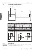
Mounting flange and shaft requirements
Frame size (C/CH)
041 042
043
041
051 052 053 054 061 062 063
Shaft material
Steel or stainless steel
Shaft yield point
N/mm²
380
(A) Ø Shaft (-0.015mm)
mm
32
45
71
(B) Ø Shaft (-0.015mm)
mm
33
46
72
(C) Ø Pilot (±0,025mm)
mm
92.065
118.065
164.065
(D) Shaft length (±0.4mm)
mm
17
48
79
110
35
60
85
110
49
83
117
(E) Shaft length (±1.5mm)
mm
61.3 92.3 123.3 154.3 82
107 132 157 104 138 172
(F) Recess
mm
> 5.5
Axial shaft movement
mm
± 0.13
Shaft radial runout
Pilot concentricity
Flange perpendicularity
0.13 mm TIR
0.10 mm TIR
0.10 mm TIR
More dimensions see pages 79, 80 and 81.
15.2.2
Mounting, Removal
Improper mounting may damage the motor and machine.The procedure is described in
the "Mounting/Removal" leaflet included with the motor.
English - 34
Servomotors Cartridge DDR
Mechanical Installation
04/2017
Kollmorgen
ENGLISH
B
C
E
A
F
D
Machine

