background image

1

IMPORTANT

Installer: These instructions are for use with the 

UK version of this product only. This Manual is the 

property of the customer and must be retained with the 

product for maintenance and operational purposes.

Product Manual

Rada Outlook

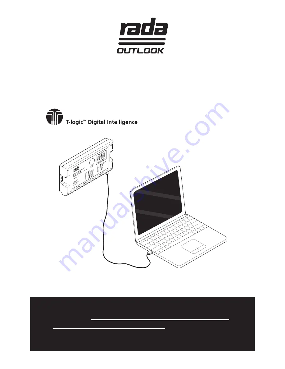
Configuration Tool and USB Cable

Summary of Contents for rada outlook

Page 1: ...s are for use with the UK version of this product only This Manual is the property of the customer and must be retained with the product for maintenance and operational purposes Product Manual Rada Ou...

Page 2: ...CONFIGURATION TOOL 9 Site Details 9 Locate Valves 11 Select Valve 12 Valve Status 12 Valve Setup 13 Outlet Setup 14 Outlet Setup Basin 15 Outlet Setup Shower 15 Outlet Setup Options 16 Extra Outlet O...

Page 3: ...l be solely responsible for the independent backup of all data information stored on Rada Outlook Notwithstanding the foregoing none of the exclusions and limitations stated above are intended to limi...

Page 4: ...CONTENTS 1 x RS485 USB Cable 1 x Installation USB Stick The cable needs to be connected to the Rada Outlook Sensor Box according to the system requirements Refer to USB Cable Installation for further...

Page 5: ...rk installations A yellow A yellow B yellow A yellow B orange B orange B brown A brown 0V black 0V black A green B green 5V red N C A orange B orange 0V black 0V black N C 5V red Internal Power withou...

Page 6: ...oth the RS485 USB Cable and Cat5 cable to the Network NET port of one Sensor Box Recommended for permanent connection 2 Connect both the RS485 Socket and Cat5 cable to the Network NET port of one Sens...

Page 7: ...Ve A B 0V Ve A NET port Sensor Box 1 1 2 3 4 1 2 3 4 red black orange yellow B 0V Ve A RS485 Socket orange black brown red RS485 USB NET port Sensor Box 2 NET port Sensor Box 3 Option 1 RS485 USB sup...

Page 8: ...ows XP SP 1 temporarily disconnect your PC from the Internet This can be done by either removing the network cable from your PC or by disabling your network card by going to the Control Panel Network...

Page 9: ...both the Mixer Valve and the PC Laptop device Double click the Rada Outlook icon on the desktop or search for and run the file Rada Outlook exe Enter the site details in the above screen and save usi...

Page 10: ...10 Enter the name of the file to be saved and press Save A new text file will be created and used automatically each time the Configuration Tool is started...

Page 11: ...re read into the Configuration Tool Select the Com Port where the RS485 USB Cable is connected Locate Valves Press Search to find all connected Sensor Boxes All devices found are listed with their net...

Page 12: ...e selected Sensor Box and Mixer Valve from any of the main screens by using the drop down menu in the top right corner The Valve Status is displayed under the title of the screen Error messages will a...

Page 13: ...sor Box to identify it usually the location of the device Input a location name up to 16 characters and press Location The Set Calibration No is used only if the Mixer Valve is required to be calibrat...

Page 14: ...14 Outlet Setup Select the outlet usage Type This screen shows how each of the six outlets are configured to operate Alter the various settings for each individual outlet...

Page 15: ...ic The outlet runs continuously if the sensor is active continuously i e hand held over the sensor Once the sensor is uncovered the outlet stops after the Run Time duration Outlet Setup Shower Set the...

Page 16: ...for Fan and Fan Run On Time Duty Flush To include the outlet when a Duty Flush Cycle is performed Outlet Setup Options Timed The outlet is turned on with the sensor and stops automatically after the...

Page 17: ...f outlets required to be active simultaneously for the fan to be switched on Fan Run On Time The length of time the fan operates after all outlets are switched off Up to a maximum of 59 mins 59 secs D...

Page 18: ...settings and the period of inactivity The system detects if an outlet is used within the Flush Interval and suspends the flush cycle automatically until the Flush Interval has expired This conserves...

Page 19: ...ss Write to transfer the settings to the Sensor Box and Mixer Valve Set Date Sets the Sensor Box s date and time to the current PC Laptop date and time Default Values Standard 3 days 01 00 02 00 02 00...

Page 20: ...The date and time of the cycle Outlet Status If the cycle was successfully performed on each of the six outlets Duty Flush successful Duty Flush failed or interrupted DutyFlushnotrequired Usuallyseenw...

Page 21: ...uration Tool software It is activated by the supervisor manually and will raise the water temperature to exceed the safe level for bathing and will scald or even kill It is therefore the responsibilit...

Page 22: ...infection cycle This will depend upon the size of washroom the PIR position and the number of outlets used The PIR system should be checked to ensure that the appropriate area is covered adequately an...

Page 23: ...fault values for both types are 2 mins 20 mins 25 mins 60 C 70 C Max Warm Up Time Target Disinfection time Disinfection Timeout Target Temperature Upper Temperature Press Read to display the current s...

Page 24: ...iod then the disinfection will be cancelled If unsure leave as default Target Temperature C The maximum temperature required to perform a successful disinfection cycle Upper Temperature C If the water...

Page 25: ...erally required when the system is either used for the first time or has not been in use for a prolonged period to make sure that the cold supply pipes are free from high levels of bacteria 1 Close co...

Page 26: ...sinfection Type to Standard Cold Inlet Supply or Exponential Cold Inlet Supply depending upon the requirments for the site conditions and perform the disinfection cycle according to the instructions i...

Page 27: ...ivated three at a time The Outlet Status Test display in the Outlet Setup screen shows which of the six outlets are currently active When the disinfection cycle has finished wait 10 seconds and press...

Page 28: ...erature and flow rate and recommence the disinfection cycle The log can be saved by using File Save A folder called Disinfection Logs is created automatically within the Site Name folder see Site Deta...

Page 29: ...lve Control PCB are replaced The calibration number is required and can be found on the Mixer Valve body Press Valve Off to turn off the Mixer Valve and enable the Calibration No to be changed Enter t...

Page 30: ...ok Configuration Tool and RS485 USB Cable We guarantee these products against any defect in materials or workmanship for the period of one year from the date of purchase For terms and conditions refer...

Page 31: ...31 NOTES...

Page 32: ...your product declines check in this guide to see if simple home maintenance is required If you require further assistance call our Customer Services Team Technical Helpdesk Service Our Customer Servic...

Reviews: