

4: Operating Procedures
46
TS_619_00 PW9000DPA S2 User Manual 13/3/17
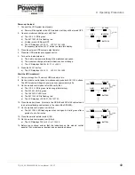
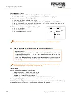
4. On all module control panels, verify that:
a) The
INVERTER
LED is extinguished.
b) The
BYPASS
LED is green.
c) The LCD displays
LOAD
NOT
PROTECTED
.
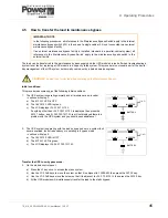
Transfer the load to maintenance bypass:
5. Close the maintenance bypass switch.
6. On the module control panel, verify that:
a) The
INVERTER
LED is red.
b) The
BYPASS
LED is green.
c) The LCD displays
MANUAL
BYP
IS
CLOSED
.
d) The audible alarm activates.
7. Press the
RESET
button (
on all UPS modules
) to cancel the audible alarm.
a) The LCD display should indicate
LOAD
NOT
PROTECTED
.
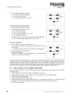
Turn off the UPS module:
8. Carry out steps 9 to 11 on each UPS module in turn.
9. On the module control panel, simultaneously press both
ON/OFF
buttons
and verify that:
a) All LEDs turn OFF except for
LINE
1
and
BATTERY
(flashing green).
10. Open the module’s parallel isolator (IA2).
11. Open the battery fuses.
(Internal in the DPA-50 and DPA-150 cabinets or in an external battery
cabinet/rack in the case of the DPA250).
The load is now connected directly to the mains supply via the maintenance bypass circuit. In the case of a single cabinet
installation using the internal maintenance bypass switch (IA1), the input/bypass supply isolators on the mains
switchboard panel must remain closed to support the load, and the UPS cabinet ‘s input/bypass and output power
terminals will remain live. Where an external maintenance bypass facility is used, the UPS system input supply can be
turned off – see the operating instructions for the bespoke external maintenance bypass facility for details.
4.6
How to shut down the complete UPS system
If the load does not require power for an extended period of time, the UPS system can be completely shut down using the
following procedure.
1. Transfer the load to the maintenance bypass as described in paragraph 4.5.
2. Isolate all load equipment by opening the load fuses or circuit breakers at the load switchgear panel.
3. Open the maintenance bypass switch.
4. Open the external UPS system output isolator.
5. Isolate the UPS system input supply. Where used, refer to the operating instructions for the bespoke external
maintenance bypass circuit for additional details of how to isolate the UPS mains supply if necessary.
6. The UPS is now voltage free.
LINE 1
LINE 2
BY PASS
INVERTER
BATTERY
LOAD
LINE 1
LINE 2
BY PASS
INVERTER
BATTERY
LOAD
LINE 1
LINE 2
BY PASS
INVERTER
BATTERY
LOAD