
3: Installation
26
TS_619_00 PW9000DPA S2 User Manual 13/3/17
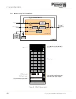
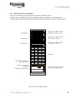
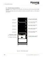
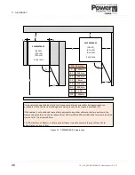
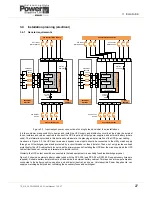
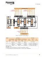
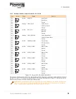
Figure 3.1 PW9000DPA S2 clearances
PW9000DPA S2
(DPA‐50)
(DPA‐150)
(DPA‐250)
REAR FANS
D
B
1
A
C1
C2
C1
It is necessary to open the door fully to remove some internal assemblies during maintenance
procedures. If the cabinet is placed against a wall ensure sufficient space is provided (C2).
If the cabinet is not positioned immediately adjacent to any other cabinet or battery enclosure, the
clearance behind the unit can be reduced from 300mm (B1) to 200mm (B2) if the total combined side
clearance (E+F) is at least 400mm.
*A TOP clearance of 400mm is only required if there is no other route at the rear of the UPS to
dissipate the cooling air flow.
PW9000DPA S2
(DPA‐50)
(DPA‐150)
(DPA‐250)
REAR FANS
B
2
E
F
D
C2
1000mm
300mm
0mm
A
B1
C1
Min. Clearance
315mm
C2
200mm
B2
400mm
E+F
115
D
*400mm
TOP
1000mm
300mm
0mm
A
B1
C1
Min. Clearance
315mm
C2
200mm
B2
400mm
E+F
115
D
*400mm
TOP