

3: Installation
38
TS_619_00 PW9000DPA S2 User Manual 13/3/17
3.5.4 Connecting the battery cables
DC cabling for the battery system(s) must be completed by an Uninterruptible Power Supplies Ltd. engineer or one of its
approved service agents.
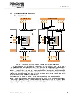
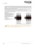
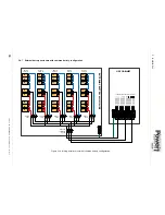
3.6
Customer Interface Board
The customer interface board is described in paragraph 2.5 with some of its common applications described in detail in
paragraph 7.2. This section deals with the connection of the dry port interface connections taken to terminal blocks X1 -
X4 which may be connected at this stage of the installation procedure.
All the on-board relays connected to these terminal blocks are rated at 60VAC / 8A and the Phoenix terminals can accept
cables of 0.5 mm².
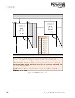
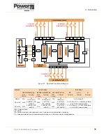
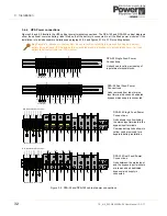
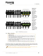
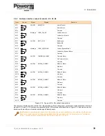
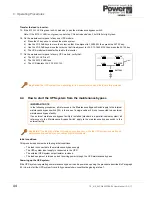
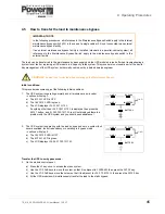
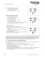
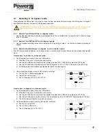
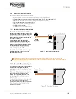
3.6.1 Customer dry-port interface terminal block – X1
X1 is a Phoenix spring terminal block and external connections should be made using s 0.5mm² cable.
Note that the ‘Remote Shut down’, ‘On-Generator’ and ‘Customer defined’ connections are described in Chapter 7.
Figure 3.13 Customer interface input connections (X1)
CAUTION: The customer interface board contain several DIP switches and jumper links which must be
configured by the commissioning engineer. Once set, DO NOT touch.
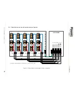
Key Point:
When the UPS cabinet is installed as part of a parallel system the customer interface board I/O is
disabled in the ‘slave’ cabinets if the system ‘Multidrop’ application is enabled. Under such circumstances the
required interface connections should be made to the board fitted in the ‘master’ module only.
Term
Contact
Signal
Function
X1/1
+3.3Vdc
Remote Shut down
(Do not remove the factory mounted bridge until external Remote Shut down is connected)
X1/2
GND
X1/3
+3.3Vdc
Generator Operation
(NC = Generator ON)
X1/4
GND
X1/5
+3.3Vdc
Customer IN 1
(Customer defined)
X1/6
GND
X1/7
+3.3Vdc
Customer IN 2
(Customer defined)
X1/8
GND
X1/9
+3.3Vdc
Battery temperature sensor
(If connected, the battery charger current depends on battery temperature)
X1/10
GND