- 36 -
71
70
69
68
13
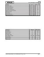
0,00 ÷ 0,10
0,8
0,10 ÷ 0,20
0,9
0,20 ÷ 0,30
1,0
0,30 ÷ 0,40
1,1
Piston
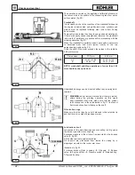
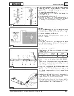
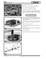
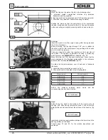
Mount the rings on the piston (fig. 68) in the following order:
1.
chromium plated compression retention ring (stamped
trademark pointing upwards)
2.
tapering retention ring (stamped word TOP pointing upwards)
3.
oil scraper ring (stamped trademark pointing upwards)
Position the piston so that the central axis of the combustion
chamber is aligned with the injector (fig. 69). Connect the piston
to the connecting rod, slightly pressing with the hand on the pin.
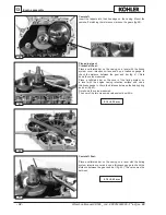
Cylinder
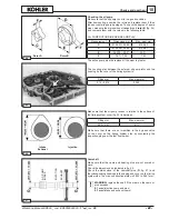
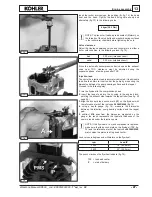
Insert the cylinder into the engine casing after having inserted
the 0.3 mm thick seal.
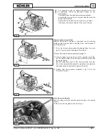
before mounting, turn the rings through 120°, one in relation to
the other, with the first compression ring pointing with its ends
on a level with the pin axis.
There is a chamfer to allow ring insertion on the lower side of
the cylinder. The operation is simplified by using a normal ring
mounting tool code
00365R0770
as indicated in fig. 70.
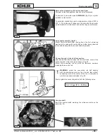
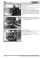
Move the piston to TDC (top dead center) and check that the
mark stamped on the flywheel corresponds to the reference
pointer of the tool code
00366R0240
(fig. 75).
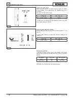
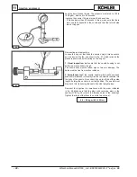
To obtain the correct clearance, use a head seal of adequate
thickness:
1.
check the piston projection as shown in fig. 71
2.
Choose the seal as indicated in the following table
Head
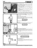
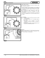
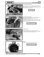
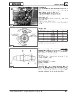
Before fixing the head to the cylinder, fit the injector into its
housing and, after having temporarily fixed it, check that the
distance the nozzle projects from the surface of the head by (fig.
72):
2,2 ÷ 2,7 mm
regulate by placing copper washers between the injector and the
bearing surface on the head.
Consult page 19 and 20 for the relative inspections and
overhauls.
Engine assembly
Measurement
Dimensions mm
NOTE: The distance between piston crown and the
corresponding head surface must be:
0,7 ÷ 0,8 mm
Workshop Manual KD500 _ cod. ED0053029390 -
1° ed
_rev.
00

