background image

- 24 - 

29

28

10

0,021 ÷ 0,059

0,10

53,0 ÷ 53,2

0,3

1,45 ÷ 2,05

Checks and overhaul

Tapets and rocker arms

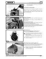
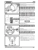
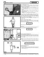
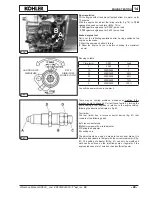
Make  sure  that  there  is  no  wear,  scoring  or  signs  of  seizure 

on  the  surfaces  of  the  tappets  (fig.  28).  Replace  the  parts  if 

necessary.

Tapet and housing coupling play:

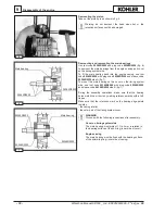
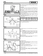
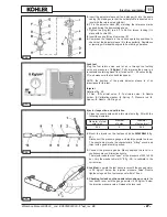
Injection pump tappets and pads

Replace the parts if the wear on their surfaces exceeds 0.1 mm 

(fig. 29).

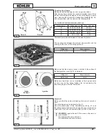
Coupling  play  between  the  tappet  and  relative  housing  in  the 

crankcase:

Fuel pump (optional)

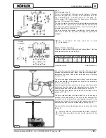
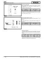
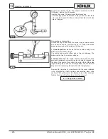
Check the projection of the AC pump rod in relation to the engine

casing surface with the canshaft eccentric in the non-operative 

position.

0,16 ÷ 0,215

0,345

Fitting mm

Max. wear mm

The rods must be straight with ball shaped surfaces at the ends 

and in good conditions (fig. 28).

Fitting mm

Max. wear mm

WARNING: the rod projection cannot be adjusted.

Rod length

mm

Wear limit

mm

Rod projection

mm

Workshop Manual KD500 _ cod. ED0053029390 - 

1° ed

_rev. 

00

Summary of Contents for KD 500

Page 1: ...KD 500 WORKSHOP MANUAL...

Page 2: ...ual assumes the following 1 The person or people performing service work on KOHLER series engines is properly trained and equipped to safely and professionally perform the subject operation 2 The pers...

Page 3: ...for the time period listed below provided there has been no abuse neglect or improper maintenance of your engine Your emission control system may include parts such as the fuel injection system and th...

Page 4: ...TERISTICS POWER TORQUE AND SPECIFIC FUEL CONSUMPTION CURVES 12 OVERALL DIMENSIONS 13 SPECIAL TOOLS 14 MAINTENANCE RECOMMENDED OIL TYPE REFILLING 15 MAINTENANCE 15 FUEL 15 RECOMMENDED OIL 16 ACEA SEQUE...

Page 5: ...ft assembly 33 Connecting rod drive shaft connection 33 Counter shaft 33 Camshaft 34 Play adjustment 34 Crankshaft float 34 Camshaft float 34 Counter shaft float optional 35 Cover on timing system sid...

Page 6: ...6 Index Workshop Manual KD500 _ cod ED0053029390 1 ed_rev 00...

Page 7: ...livery valve Wrong injector setting Excessive plunger blow by Jammed injection pump delivery control Wrong injection pump setting Oil level too high Jammed pressure relief valve Worn oil pump Air insi...

Page 8: ...ldings or other machines SAFETY REGULATIONS Children and animals must be kept at a sufficient distance from the machine to prevent any danger resulting from its operation Fuel is flammable so the tank...

Page 9: ...g order to limit environmental and noise pollution When discontinuing use of the engine select all components according to their chemical characteristics and dispose of them separately Some phases may...

Page 10: ...tly on the engine It contains the following information A Manufacturer s identity B Engine type C Engine serial number D Maximum operating speed E Number of the customer version form K F Approval data...

Page 11: ...PTO ratio Camshaft PTO ratio Crankshaft main PTO rotation Camshaft main PTO rotation Max torque Fuel consumption max torque Oil consumption Capacity of standard oil sump Recommended battery 12V in st...

Page 12: ...ith constant speed and constant load MN Torque at N power MB Torque at NB power MA Torque at NA power C Specific fuel consumption at NB power The above power values refer to an engine fitted with air...

Page 13: ...IRECTION OF ROTATION OPTIONAL P T O ON CAMSHAFT WITH CLOCKWISE DIRECTION OF ROTATION GRAVITY CENTER OF THE ENGINE AUXILIARY P T O FOR HYDRAULIC PUMPS Workshop Manual KD500 _ cod ED0053029390 1 ed_rev...

Page 14: ...LS Failure Flywheel puller Tool to mount and demount main bearings Plug to mount and demount main bearings Sleeve to insert main bearings Piston mounting tool Crankshaft gear puller Punch to insert By...

Page 15: ...face well away from the plug to prevent harmful vapours from being inhaled Dispose of fuel in the correct way and do not litter as it is highly polluting FUEL When refuelling it is advisable to use a...

Page 16: ...er the bearings and all moving parts increases if oil whose characteristics differ from the recommended type is used or if the oil is not regularly changed All this notably reduces engine life Oil vis...

Page 17: ...be removed when the stop lever has been turned to the stop position To do this the pump must be pressed towards the housing as shown in fig 2 Flywheel extraction Remove the fuel tank the air conveyor...

Page 18: ...aring on the cover on the timing system side use tool code 00365R0900 with plug code 00366R0220 and sleeve code 00366R0230 side B fig 7 During the assembly operations make sure that the bearing holes...

Page 19: ...with guide mounted measurements in mm Check the dimensions of the valve stem fig 10 and the play between the guide and valve Ream the guide to the dimensions indicated in the table Change the guide a...

Page 20: ...Make sure that there are no evident signs of wear on the contacting surfaces Replace the parts if necessary Cylinder In special cast iron with integral liner Use a bore gauge to check the two interna...

Page 21: ...roximately 11 mm 86 915 86 835 Check the play between cylinder and piston Replace the parts if play exceeds 0 150 mm Play between pin and piston mm Piston ring Max wear mm 1st Compression 2nd Compress...

Page 22: ...e Undersized bearings can be mounted without any reaming work required WARNING do not remove material from the main journal shims during the grinding operation as this would alter crankshaft float Als...

Page 23: ...oil pump recess in relation to the surface of the timing system cover fig 25 is between Camshaft Make sure that the cams and bearing pins are not scored or worn Check the dimensions as indicated in fi...

Page 24: ...0 1 mm fig 29 Coupling play between the tappet and relative housing in the crankcase Fuel pump optional Check the projection of the AC pump rod in relation to the engine casing surface with the cansh...

Page 25: ...pipe 3 Fuel filter 4 Injection pump 5 Fuel return pipe 6 Injector 7 Injection pipe 8 Fuel pipe Injection pump Illustration in fig 31 1 Delivery union 2 Filler 3 Valve spring 4 Delivery valve 5 Washers...

Page 26: ...7 sec Injection pump calibration fig 34 When the adjuster sleeve is 10 5 mm from the stop position and the pump spins at 1 500 rpm the amount of fuel for 1 000 deliveries must be between 25 5 29 cc Re...

Page 27: ...ilter 2 Fuel inlet union 3 Fuel return union 4 Nozzle holder 5 Calibration washer 6 Spring 7 Pressure rod 8 Spacer 9 Nozzle 10 Ring nut Injector inspection and calibration 1 Clean the nozzle holes wit...

Page 28: ...ormed or excessively rough The nozzle body must not show signs of wear or damage The holes must be free from carbon residues 2 Smoothness test the nozzle needle which will have been previously immerse...

Page 29: ...he regulator and alternator are correct and in good conditions 2 detach the wire from the remote control switch from the terminal and fit on a d c amperometer A fig 43 3 connect a d c voltmeter to the...

Page 30: ...than this it means that the rotor is demagnetized and that the alternator must be replaced Warning 1 the alternator does not deliver current when the yellow cables are isolated 2 the alternator burns...

Page 31: ...1 Fit on the oil drain plugs without tightening them too much max 2 Kgm to prevent damage to the threads 2 Mount the main bearing as indicated at page 18 3 Fit the benzing ring on to the pin of the r...

Page 32: ...ass valve using tool code 00366R0210 fig 54 mount the by pass check screw with Loctite 648 mount the bypass valve inspection plug on the outside of the cover on the timing system side 5 Fit the retain...

Page 33: ...48 and after having inserted the needle bearing and the second shimming washer Connecting rod drive shaft connection After having fitted the bearings into the small end connect the connecting rod to t...

Page 34: ...red Place a calibrated bar on the cover of the timing system on a level with the engine casing retention surface and use a thickness gauge to check the distance between the bearing ring and bar fig 62...

Page 35: ...e timing system cover fig 65 Place the cover on the casing Insert the cover fixing screws making sure that the five shorter ones 40 mm are mounted in the top part of the cover Tighten to the following...

Page 36: ...the lower side of the cylinder The operation is simplified by using a normal ring mounting tool code 00365R0770 as indicated in fig 70 Move the piston to TDC top dead center and check that the mark s...

Page 37: ...lead is accurately adjusted it is advisable to define the shims to insert under the pump by measuring the dimension between the pump bearing surface and the tappet Proceed in the following way 1 turn...

Page 38: ...e by tightening the nut that holds the relative bracket Match the marks made during the demounting phase see section Removing the injection pump page 17 Warning consult section Braked engine test page...

Page 39: ...blems slowness or misfiring if the injection pump is changed Correct these faults by turning the pump casing a few degrees in relation to the engine casing following the directions indicated in fig 80...

Page 40: ...ase all unpainted parts Loosen belt Wrap the engine in a plastic film Store in a dry place if possible not directly on the soil and far from high voltage electric lines Permanent protection over 6 mon...

Page 41: ...HARTS Adjustments Camshaft float Countershaft float Crankshaft float Connecting rod float Valve clearance hot cold Valve recessing Injector projection Piston projection Couplings Camshaft and plugs Co...

Page 42: ...0 72 1 23 2 02 3 02 3 88 5 36 9 09 13 80 21 00 26 30 36 60 44 40 56 90 4 x 0 70 5 x 0 80 6 x 1 00 7 x 1 00 8 x 1 25 9 x 1 25 10 x 1 50 13 x 1 75 14 x 2 00 16 x 2 00 18 x 2 50 20 x 2 50 22 x 2 50 24 x...

Page 43: ...ises by the values indicated in the following table in relation to TDC dimension h fig 2 8 Remove the injection tube and mount the capillary tube code 00365R0940 on the injection pump delivery fitting...

Page 44: ...SERVICE INFORMATION IN U S AND CANADA CALL 1 800 544 2444 KohlerEngines com FORM NO ED0053029390 ISSUED 04 07 2012 REVISED 00 DATE 04 07 2012 Translated from the original manual in Italian language Da...

Reviews: