11.4
Section 11
Reassembly
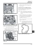
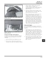
Figure 11-11a. Applying Camshaft Lubricant to
Bottom of Lifters.
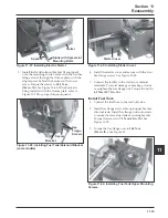
3. Note the mark or tag identifying the hydraulic
lifters as either intake or exhaust. Install the
hydraulic lifters into the crankcase. See Figure
11-11b.
NOTE:
Install lifters in the same position as
before disassembly. The exhaust lifters
are located on the output shaft (oil pan)
side of the engine while the intake lifters
are located on the fan side of the engine.
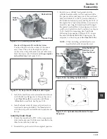
Figure 11-9. Installing Connecting Rod Fasteners.
6. Rotate the crankshaft until the piston is at top
dead center (TDC) in the cylinder bore.
Install Balance Shaft
1. Lubricate the balance shaft bearing surfaces of the
crankcase and balance shaft with engine oil.
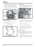
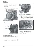
2. Align the timing mark on the balance shaft gear
and the larger gear on the crankshaft. Lower the
balance shaft into the bearing surface in the
crankcase.
3. Make sure the balance shaft gear, large crankshaft
gear and the governor gear teeth mesh and the
timing marks are aligned. See Figure 11-10.
Install Hydraulic Lifters and Camshaft
1. See
Hydraulic Lifters
in Section 10 for lifter
preparation (bleed down) procedures.
2. Apply camshaft lubricant (Kohler Part No.
25 357 14-S
) to the bottom surface of each lifter.
See Figure 11-11a. Lubricate the hydraulic lifters
and the lifter bores in the crankcase with engine
oil.
Connecting
Rod Cap
Crankshaft Timing
Mark (Large Crankgear)
Balance Shaft
Timing Mark
Figure 11-10. Aligning Timing Marks on Crank Gear
and Balance Shaft Gear.
Figure 11-11b. Installing Hydraulic Lifters.
Connecting
Rod Bolts


