TP-6069 6/03
24
Section 6 Electrical System
6.5 Battery
Batteries and their installation must conform to USCG
Regulations 183.420 (a) through (g). Provide generator
sets with batteries separate from the propulsion
engine’s whenever possible.
The starting/charging
systems of both the generator set and the engine must
have a common negative (--) ground.
USCG
Regulation
183.415,
Grounding,
requires
connection of a common conductor to each grounded
cranking-motor circuit. Size the conductor to match the
larger of the engine’s two battery cables. Figure 6-5 lists
cable sizes for generator set battery connections at
various ambient temperatures. Connecting a common
conductor to each grounded cranking motor circuit
prevents the starting motor current from using
alternative electrical paths should the cranking motor
ground circuit be restricted or open because of oxidation
or loose hardware. Alternative electrical paths include
metallic fuel lines that can pose a fire hazard. See
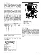
Figure 6-7 and Section 7 for battery connections to the
generator set.
Distance between
Cable Size (AWG)
Distance between
Generator Set
and Battery m (ft.)
At –18
°
C
(0
°
F)
At 0
°
C
(32
°
F)
At 24
°
C
(75
°
F)
12.2
(40)
00
0
1
9.1
(30)
0
1
2
7.6
(25)
1
2
4
6.1
(20)
2
2
6
4.6
(15)
2
4
6
3.0
(10)
4
6
8
1.5
(5)
6
6
8
0.8
(2.5)
8
8
8
Figure 6-5
Battery Cable Sizes
Kohler Co. recommends using one 12-volt or 24-volt
battery (as the spec requires) to start the generator. See
Figure 6-6 for minimum cold cranking amps (CCA)
recommendations.
12-Volt Starting Battery Size CCA
at --18
°
C (0
°
F) or 100 Amp. Hr.
Models
CCA
3.5–20EFOZ and
4--24EOZ
500
23/27/100/125EFOZ and
28/32/125/150EOZ
800
33--80EFOZ and
40--99EOZ
640
Figure 6-6
Battery Recommendations
1
3
2
4
5
TP-5586-6
1. Starter solenoid
2. Battery positive (+) connection
3. Equipment ground
4. Battery negative (--) connection
5. Engine block mount
Figure 6-7
Battery Connections (5EOZ/4EFOZ
model shown)
6.6 Wiring
Use only stranded copper wire.
Conform to USCG
Regulations 183.425 through 183.460 for wire gauges
and insulation, conductor temperature ratings, sheath
stripping, conductor support and protection, conductor
terminals and splices, and over-current protection
(circuit breakers, fuses). Use rubber grommets and
cable ties as necessary to protect and secure the wire
from sharp objects, the exhaust system, and moving
parts.
Summary of Contents for 100EFOZ
Page 2: ......
Page 4: ......
Page 10: ...TP 6069 6 03 VI Safety Precautions and Instructions Notes ...
Page 12: ...TP 6069 6 03 2 Section 1 Introduction Notes ...
Page 14: ...TP 6069 6 03 4 Section 2 Location and Mounting Notes ...
Page 20: ...TP 6069 6 03 10 Section 3 Cooling System Notes ...
Page 26: ...TP 6069 6 03 16 Section 4 Exhaust System Notes ...
Page 38: ...TP 6069 6 03 28 Section 6 Electrical System Notes ...
Page 84: ...TP 6069 6 03 74 Section 8 Reconnection Adjustments Notes ...
Page 89: ......
Page 90: ......
Page 91: ......


