TP-6069 6/03
3
Section 2 Location and Mounting
Section 2 Location and Mounting
2.1 General Considerations
The key to installation is location. Before making final
plans for locating a generator set, consider the
following.
Installation Location Considerations
1. Choose a location that allows adequate space for
cooling and exhaust system installation, fuel
system installation, ventilation, and service access
to the generator set (engine and generator).
2. Use craft stringers or other available structural
members capable of supporting the generator set’s
weight.
3. Seal the generator set compartment from the cabin
to prevent exhaust gases and fuel vapors from
entering the cabin.
See the current generator set specification sheet or
Section 7 of this manual for generator set dimensions
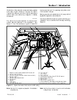
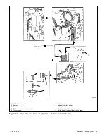
and weights. See Figure 1-1 for a typical installation.
m:is:101:001
2.2 Location
Locate the generator set to allow easy service access to
the generator set’s engine, controller, cooling, and fuel
system components. The engine compartment is often
the ideal location for the generator set if the propulsion
engine(s) does not obstruct access to the generator set
and controller.
Marine Generator Set Installations in
European Union Member Countries
This generator set is specifically intended and approved
for
installation
below
the
deck
in
the
engine
compartment.
Installation above the deck and/or
outdoors would constitute a violation of European Union
Directive 2000/14/EC noise emission standard.
Allow clearance for vibration and cooling during
operation.
Allow a minimum of 38 mm (1.5 in.)
clearance on all sides (top, front, rear, and sides) of a
generator set without an optional sound shield. Refer to
the instruction sheet for minimum clearances for
sound-shielded units. Also, allow space for the power
takeoff (PTO) option, if equipped.
Diesel generator sets are not ignition-protected. USCG
Regulation 183.410 requires ignition-protected devices
only in gasoline/gaseous-fueled environments.
2.3 Mounting
Mount the generator set as high as possible to avoid
contact with bilge splash and lower-lying vapors and to
allow for downward pitch of the exhaust line toward the
exhaust outlet.
Craft stringers generally provide the best generator set
support.
Ensure that the structural members can
support the generator set’s weight and withstand its
vibration.
The generator set includes vibration mounts and a
mounting tray or skid.
If desired, install additional
vibration isolating pads underneath the generator set’s
base.
Use the four mounting holes in the mounting tray to
mount the generator set securely to the craft.
For angular operating limits, consult the operation
manual.
Summary of Contents for 100EFOZ
Page 2: ......
Page 4: ......
Page 10: ...TP 6069 6 03 VI Safety Precautions and Instructions Notes ...
Page 12: ...TP 6069 6 03 2 Section 1 Introduction Notes ...
Page 14: ...TP 6069 6 03 4 Section 2 Location and Mounting Notes ...
Page 20: ...TP 6069 6 03 10 Section 3 Cooling System Notes ...
Page 26: ...TP 6069 6 03 16 Section 4 Exhaust System Notes ...
Page 38: ...TP 6069 6 03 28 Section 6 Electrical System Notes ...
Page 84: ...TP 6069 6 03 74 Section 8 Reconnection Adjustments Notes ...
Page 89: ......
Page 90: ......
Page 91: ......


