background image

4

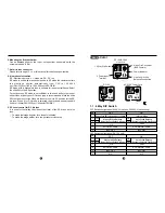
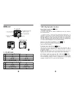
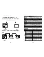
Adjustment

Lever

Front

1. CCD Protection Cover

Leave the cover in place when the lens is not installed. Take it off to fit the
lens.

2. C&CS mount

This holder moves back and forth by sliding the adjustment lever forwards
or backwards.
This mechanism is designed for the purpose of using all types of C-Mount
or CS-Mount lenses of different manufacturers. Mount the lens on the
holder firmly. It is set to CS-Mount position at the factory. Loosen the
adjustment lever by turning it counter clockwise a little bit in order to adjust
the C&CS mount holder. Set the focus and lock the lever.

3. Adjustment Lever

4. Flange back focus alignment area for C-Mount lens

The mount offers 0.5mm of extra tolerance to enable any type of non-
standard C-Mount lens to be focused. Loosen the adjustment lever by
turning it counter clockwise a little bit for fine tune focus.

5. Flange back focus alignment area for CS-Mount lens

The mount offers 0.5mm of extra tolerance to enable any type of non-
standard CS-Mount lens to be focused. Loosen the adjustment lever by
turning it counter clockwise a little bit for fine tune focus.

Name of each part & Functions

3

Warning !

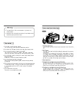
To prevent the risk of fire or shock hazard, do not expose  this 

camera to water.

Installation of this unit should be carried out by a qualified personnel 

and should conform to the local codes.

Precautions

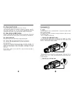
1. Do not drop or shake the carton severely.

The box cannot give perfect protection against heavy shocks.

2. Do not touch the CCD glass by hand, as this may give a blurred picture.

3. Do not expose the camera to water or other liquids.

It can cause fire or electric shock. If water or other liquids contaminate 
the unit, dry it quickly as it can corrode the electrical components  inside.

4. Do not install the camera in the wet area or area of high humidity without 

adequate protection.
Moisture can corrode the electrical components  inside.

5. Do not turn the camera to face strong light.

Direct sunlight or strong reflected light can cause blooming or smearing 
of the picture.

6. Do not install or use the camera in an environment of extreme temperature. 

In temperatures of below -10

°

C use an external housing with heater built 

in. In a temperatures of over +60

°

C, cool the camera with ventilation 

apparatus.

7. Do not disassemble the camera.

There are no user serviceable parts inside.

Summary of Contents for KCB SERIES

Page 1: ...www kocom co kr KCC KCB Series Cameras Manual ...

Page 2: ... 12 DC12V Only KCC 340 24 DC12V AC24V Non polarity Dynamic power input KCC 340 230L AC230V AC200 AC240V KCC 340X Series 480 TV Lines 0 01 Lux F1 4 with EX view HAD CCD KCC 340X 12 DC12V Only KCC 340X 24 DC12V AC24V Non polarity Dynamic power input KCC 340X 230L AC230V AC200 AC240V IR Sensitive for Day Night application Model nr IR ex KCC340 24 IR KCB 34 Series 420 TV Lines 0 05 Lux F1 4 KCB 34 12 ...

Page 3: ...ounter clockwise a little bit for fine tune focus Name of each part Functions 3 Warning To prevent the risk of fire or shock hazard do not expose this camera to water Installation of this unit should be carried out by a qualified personnel and should conform to the local codes Precautions 1 Do not drop or shake the carton severely The box cannot give perfect protection against heavy shocks 2 Do no...

Page 4: ...electronic shutter speed is fixed to 1 50sec PAL CCIR or 1 60sec NTSC EIA 9 DC Level control for DC Iris lens It is used for controlling the video output level of the DC driven auto iris lens To make the image brighter turn the pot clockwise To make the image darker turn the pot counter clockwise 1 1 6 Way DIP Switch DIP Switch configuration 24V AC LineLock 230V AC LineLock only DIP Switch configu...

Page 5: ...s not used for security applications These two functions cannot be adjusted at the same time Adjust each mode in turn 8 7 Color 6 Way Dip Switch Functions Sync Mode Selection L L INT INT Internal Sync Mode This mode is used when the camera is installed outoor with one camera to one monitor operation L L Line Lock Mode To work with other cameras using 24VAC and 230VAC power it is required to synchr...

Page 6: ...e of one camera with one monitor under fluorescent lighting the picture is affected by the 24VAC power frequency in INT mode A flickering picture may result from this condition Set Dip S W to L L mode to remove this problem It is set to L L at the factory Gamma Correction Select Mode 0 45 1 0 Select 1 0 when the picture needs to be darker in contrast It is set to 0 45 at the factory Automatic Gain...

Page 7: ...l provides connections for DC 12V or AC 24V It is not polarity sensitive The unit has a wide power tolerance within DC 10V DC 40V or within AC 15V AC 30V It is not a special requirement to use a regurated power supply but using a regurated supply is recommended 2 3 Video Out Jack BNC Female Connect Coaxial cable from this BNC connector to the monitor Use a high quality coaxial video cable to ensur...

Page 8: ...sure to set S W to DC position before you operate the camera with a DC lens DC level control is on the side of the camera Please do not touch the DC Level control when using a fixed or Video iris type of lens The camera is set to DC at the factory Adjust the pot up or down only when you need the picture to look brighter or darker depending on the situation Generally there is no need to adjust the ...

Page 9: ...any additional information CS Mount C Mount 15 2 16 3 How to connect power 3 1 Please check the model and power specification before connecting the power 3 2 AC24V power The camera has a common power input connector for both 12VDC and 24VAC The power input is non polarized 3 3 The unit has a wide power tolerance within DC 10V DC 40V or within AC 15V AC 30V 3 4 DC 12V power Use regulated DC 12V pow...

Page 10: ...D 0 5 Lux F2 0 or 0 1 Lux at F1 4 Option 0 1 Lux F2 0 or 0 02 Lux at F1 4 EX View HAD CCD Version ON OFF by Dip Switch NTSC 1 60 1 100 000 sec PAL 1 50 1 100 000 sec Standard 0 45 Switchable 1 0 by Dip Switch Standard 2100 K 8200 K Auto Manual setting by Dip S W Up Down by Push BTN Standard 8dB 30dB Auto Maximum by Dip switch 0 005 80 000 hours White Balance Auto WB Manual adjustment 14 F 122 F 10...

Page 11: ... 12 KCB 340 24 KCB 340 230 DC12V DC12V AC24V 4V Dual AC230V 30V DC12V DC12V AC24V 4V Dual AC230V 30V 90mA 90mA 30mA 90mA 100mA 32mA Video Iris ESC DC Iris C Mount 17 5mm Frange back CS Mount 12 5mm Frange back Fine focus 1 0mm 240 ON OFF 0 45 1 0 ON OFF STD MAX BNC Red LED Screw Joint YES 4Way Slide 4Pin Jack VI ES DC DC Level 220 0 45 1 0 ON OFF STD MAX BNC Red LED Screw Joint 4Way Slide 4Pin Jac...

Page 12: ... pointer towards an area where too much light comes in Adjust the direction of the camera in this case Please check if the back focus of the lens is set correctly When the picture is flickering Please check if the camera is pointed at fluorescent lighting or bright sunlight Use a visor or adjust the direction of the camera in this case Please check if the Auto iris lens is selected correctly on th...

Reviews: