

2
18
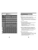
Specification (Color)
MODEL
KCC-34(12)
KCC-34(24)
KCC-34(230L) KCC-340(12)
KCC-340(24) KCC-340(230L)
DC12V
DC12V-AC24V Dynamic
AC230V
DC12V
DC12V-AC24V Dynamic
AC230V
130
mA
130
mA,
82
mA
20
mA
150
mA
150
mA,
95
mA
23
mA
Video Iris/ESC/DC Iris
C-Mount (17.5mm Frange back) ~ CS-Mount (12.5mm Frange back) & Fine focus 1.0mm
240
Yes
Yes
Yes
Yes
ON/OFF
STD/MAX
0.45/1.0
ON/OFF
BNC
Red LED
Screw Joint
Up/Down
Up/Down
6 Way
4Pin Jack
VI ES DC
DC Level
220
Yes
Yes
12V DC Only
ON/OFF
STD/MAX
0.45/1.0
BNC
Red LED
Screw Joint
Up/Down
6 Way
4Pin Jack
VI ES DC
DC Level
220
Yes
Yes
12V DC Only
ON/OFF
STD/MAX
0.45/1.0
BNC
Red LED
Screw Joint
Up/Down
6 Way
4Pin Jack
VI ES DC
DC Level
420
Yes
Yes
Yes
ON/OFF
STD/MAX
0.45/1.0
BNC
Red LED
230V AC VDE Code
Up/Down
Up/Down
6 Way
4Pin Jack
VI ES DC
DC Level
240
Yes
Yes
Yes
Yes
ON/OFF
STD/MAX
0.45/1.0
ON/OFF
BNC
Red LED
Screw Joint
Up/Down
Up/Down
6 Way
4Pin Jack
VI ES DC
DC Level
420
Yes
Yes
Yes
ON/OFF
STD/MAX
0.45/1.0
BNC
Red LED
230V AC VDE Code
Up/Down
Up/Down
6 Way
4Pin Jack
VI ES DC
DC Level
1/3" SONY HAD IT CCD Option : 1/3" EX-View HAD CCD, SONY
NTSC:512(H)X492(V) PAL:500(H)X582(V) NTSC:768(H)X494(V) PAL:752(H)X582(V)
380 TV Lines
480 TV Lines
Internal
Internal/Line Lock Line Lock Only
Internal
Internal/Line Lock Line Lock Only
NTSC 525 Lines PAL 625 Lines 2:1 Interlaced
1.0Vp-p Composite. 75 Ohms
More then 50 dB (AGC Off)
STD:0.5 Lux/F2.0 or 0.1 Lux at F1.4 Option:0.1 Lux/F2.0 or 0.02 Lux at F1.4(EX-View HAD CCD Version)
ON/OFF by Dip Switch
NTSC : 1/60~1/100,000 sec PAL : 1/50~1/100,000 sec
Standard
0.45 Switchable
1.0 by Dip Switch
Standard 2100°K ~ 8200°K Auto Manual setting by Dip S/W & Up/Down by Push BTN
Standard : 8dB~30dB Auto Maximum by Dip switch
0.005%
80,000 hours
White Balance Auto/WB Manual adjustment
14° F~122° F ( -10° C~ + 50° C )
Within 90% RH
50(W) x 50(V) x 100(L)
Image sensor
Effective Pixels
H.Resolution
Synchronizing system
Scanning system
Video output
S/N ratio
Min. Illumination
BLC
Shutter Speed
Gamma correction
White Balance
Gain Control
Smear Effect
MTBF
Power source
Operating current
Lens
Iris Control
Operating Temperature
Humidity
Measurement(mm)
Weight(Approx.g)
IR Sensitivity
Audio
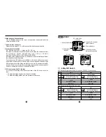
Dual Power 12~24
Line Lock
BLC
AGC
Gamma
WBA / WBM
Line Lock
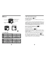
Video Out
Power Indicator
Power Input terminal
Line phase push BTN
W/B adjust push BTN
Dip S/W
Auto Iris jack
Iris Mode Slide S/W
DC Iris Adjust volume
Optional
Features
Dip S/W
Control
Rear
Pannel
Side
Pannel
1
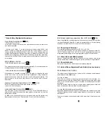
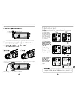
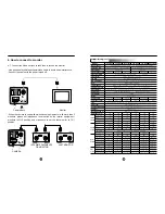
4. How to connect to monitor
4-1. Connect the Video out jack to the Video In jack on the monitor.
- Use good quality shielded coaxial video cable to avoid noise interference.
- Connect the cable with the power turned off.
- When the camera is used with multi-channel equipment or with more than 2
monitors, please set impedance level switch on the interim equipment /
monitors to HI-Z position and make sure to set the last monitor to 75
position.
Camera Back
Monitor
INTERIM EQUIPMENTS
OR MONITOR
LAST MONITOR
CAMERA
17


