


Push the call button and
communicate with the door camera.
(Call time : 3 minutes)
Press the call button while
monitoring and start to communicate
with the calling camera.
Press the call button again
and stop the communication with
the calling camera.
12
13
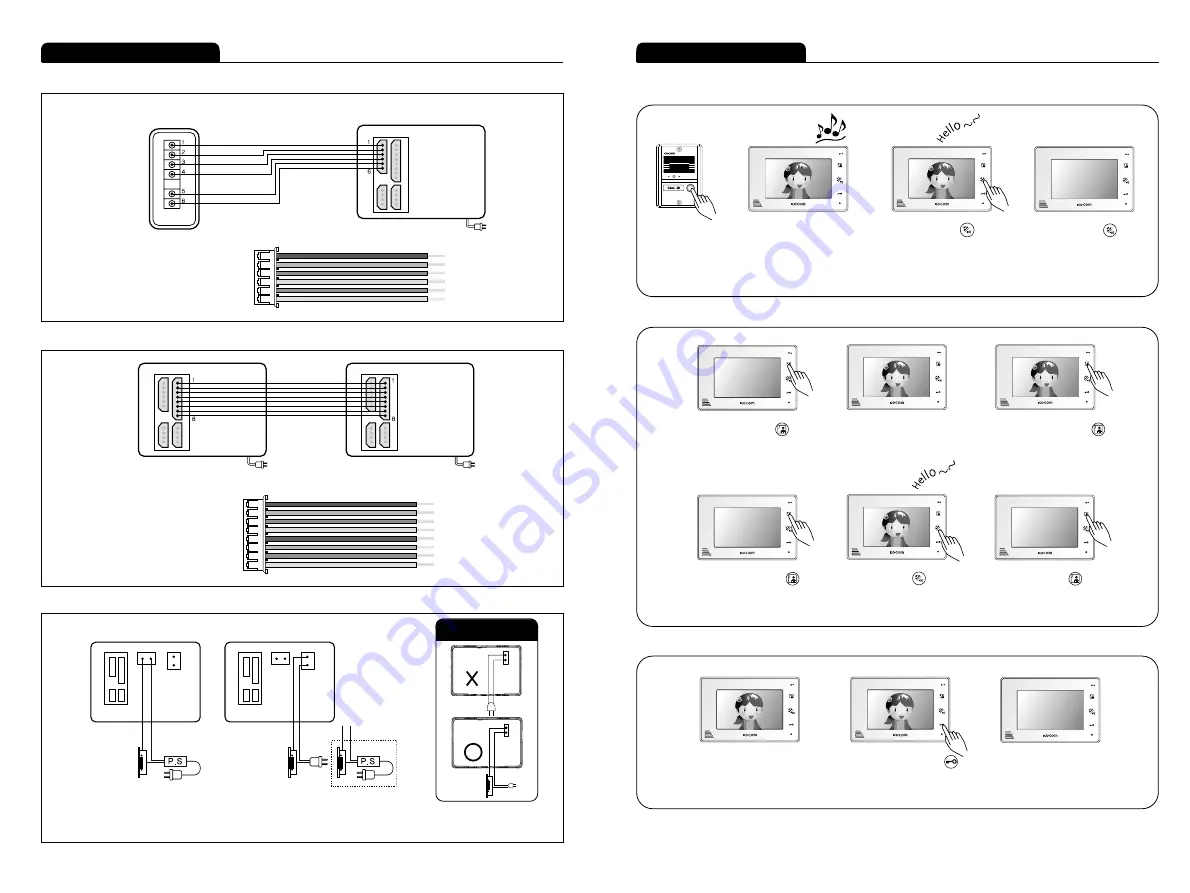
Product connection diagram
■ Sub audio phone connection
■ Ex_monitor connection
■ Door lock connection
Instructions for operation
■ Communication with door camera
Push the call button.
The camera melody is
turned on.
You can hear call sound from
all connected monitors, and
camera image comes out on
screen.
(Standby time : 2 minutes)
Push the call button again
and stop the communication.
�
�
�
■ Camera monitoring
Push the monitor button when
there is no image on monitor screen.
Camera image appears on screen.
(Monitoring time : 1 minute)
Push the monitoring button
2 times and the image of camera
2 appears.
Push the monitoring button
again and stop the communication.
�
�
�
�
■ Opening door automatically
While communicating with
a camera,
Press the door open button
and open automatically the
door of the camera.
About 5 seconds after pushing
the button, call ends automatically.
�
�
※ Caution of Door Lock
1. VCC
2. GND
3. AUDIO
4. VCC
5. DOOR1
6. DOOR2
1. VCC1
2. GND
3. AUDIO1
4. VIDEO1
5. VCC2
6. AUDIO2
7. VIDEO2
8. DATA
Sub audio phone
(KDP-602G)
Monitor
- Sub audio phone connection wire spec
- Ex_Monitor connection wire spec
Monitor
Monitor
Door 2 : DC Door Lock
(Camera 2 door open)
Door 1 : AC or DC Door Lock
(Camera 1 door open)


