Kobold ZOE series Operating Manual Download Page 24

ZOE 

Page 24 


ZOE K04/0718 

9.3 Signal 

9.3.1 

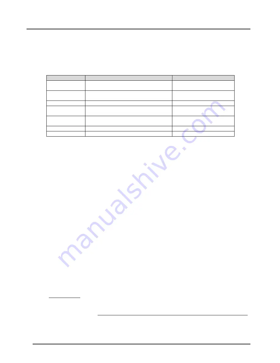
Signal / Sensor type 

The pulse input can be optimally customized to different sensor types in Menu, so that 
at the time of connection no further additional wiring is required for correct function. 


Menu Parameter 

Sensor type 

Internal wiring 

NPN 

Hall sensor, Reed switch and all NPN 
sensors 

Pull-Up resistor 

Coil 

For induction coil  
(Amplitude > 20 mVpp) 

High impedance input 

PNP 

For all PNP-Sensors Pull-Down 

resistor 

Active signal 

For all sensors with active output signal, 
e.g. (push-pull outputs) 


NAMUR 

For sensors with 2-wire interface according 
to EN 60947-5-6 (NAMUR) 

Pull-Down resistor 1kOhm 

Reed 

Reed switch 

Pull-Up resistor 

Hall 

For Hall sensors 

Pull-Up resistor 

9.3.2 

Signal / Timeout 

For the detection of input signals, the period duration of signal is determined within a 
measuring cycle i.e. Refresh time. However, if within the "refresh time" the input period 
is not complete i.e. if the input signal has a frequency lower than the frequency 
determined from the ‘’Refresh time’’, then the flow indicator is set to "0". In the shortest 
"refresh time" of 1 seconds, only a minimum input frequency of 1 Hz is recorded. In 
order to detect even lower frequencies, "Input Timeout" parameter can be configured 
up to 20 s. After the completion of „Refresh time“, the signal processing waits for the 
full input period until the additional waiting period is expired. It should be noted that by 
increasing the waiting time, the reaction time for the detection, for example, a flow 
failure is greatly increased. The "Input Timeout" should only be large enough so that 
the smallest frequency signal from the connected sensors can be detected. 
 

9.3.3 

Signal / Filter 

In case of discontinuous input signals, the integrated filter function can filter the display 
of flow rates, the analogue output and the switching outputs (only options E3/). Despite 
filtering effect, the reaction time to rapid changes in the flow rate can be kept low by 
appropriate choice of filter parameters. 
The time base for the filtering function is the "Refresh time". The filter function 
operates on the principle of "moving average", where the parameter "filter factor" 
specifies the number of measuring values which are used to calculate the current flow 
value. 
If "filter factor" is set to "1", the filter function is virtually eliminated. 

 
For example : 

Filterfactor

“ = 3, „

Refreshtime

= 1,0s 


Filtered measured value 

=

Current measured value + Previous measured value + Last to the previous measured value  

3


The correct flow value is displayed after 3 x 1 =3 s. 


Summary of Contents for ZOE series

Page 1: ...Operating Manual for Flow Totalizer Model ZOE...

Page 2: ...d Menu Structure 18 8 1 Overall 18 8 2 Measuring Mode 18 8 3 Menu Mode 19 9 Instrument Parameters 21 9 1 End of instrument parameterization 21 9 2 Overview of menu functions instrument parameters 22 9...

Page 3: ...e measuring unit should be used only when the machines fulfil the EC machine guidelines 2 1 Notice according to the Battery Law Old batteries do not belong in household waste You can send the batterie...

Page 4: ...culation display and transfer of calculations and flow rates of flow meters with pulse or frequency outputs The instruments display flow rate day counter resettable and total counter in the operator s...

Page 5: ...n x x Supply voltage DC supply x Battery operation x x Sensor supply only with external supply 8 V Electrical outputs only with external supply Pulse output x LCD Display Selectable units x X Decimal...

Page 6: ...r NPT are available for electric connection in case of electronics with plastic housing To use these cable inlets the existing factory protection caps must be broken with a tool e g screwdriver and a...

Page 7: ...3 6V 2200mAh Size AA ext Batt Service 7 2 Overview of Terminals ZOE ZX with Supply option B and 3 Supply option B only battery either 1 x 3 6V or 2 x 1 5V Supply option 3 with battery either 1 x 3 6V...

Page 8: ...option ZOE ZX can also be powered by a battery In battery mode the device function scope is relatively limited Pulse output is not available The backlight of the display is switched off and cannot be...

Page 9: ...Sensor Inputs 7 4 1 Active pulse signal Power Supply External DC Supply Signal input setting ACTIVE SIGNAL Wiring for ZOE ZE with Supply option 3 Wiring for ZOE Z with Supply option B Battery 1 5V Si...

Page 10: ...ZOE Page 10 ZOE K04 0718 7 4 2 Hall Sensor NPN and PNP Sensors Power supply only external DC supply Signal input setting HALL Signal input setting NPN Signal input setting PNP Wiring for ZOE ZE...

Page 11: ...ZOE ZOE K04 0718 Page 11 7 4 3 Reed switch Signal input setting REED Wiring for ZOE ZE with Supply option 3 Wiring for ZOE Z with Supply option B...

Page 12: ...supply External DC supply and battery operation Battery operation reduces battery life Signal input setting COIL Wiring for ZOE ZE with Supply option 3 The connection of the DOT turbine wheel flowmet...

Page 13: ...ZOE ZOE K04 0718 Page 13 7 4 5 Namur Sensor Power supply only external DC supply Signal input setting NAMUR Wiring for ZOE ZE with Supply option 3 Battery 3 6V 2200mAh Size AA...

Page 14: ...ZOE Page 14 ZOE K04 0718 7 4 6 Transducer model UMF2 Power supply only external DC supply Signal input setting NPN Wiring for ZOE ZE with Supply option 3 5 4 Battery 3 6V 2200mAh Size AA...

Page 15: ...hrough a an active control input or b Carried out by a passive N O contact In both cases the function will be activated on switching from HIGH to LOW level falling edge When using an active control si...

Page 16: ...ZOE Page 16 ZOE K04 0718 Wiring for ZOE ZE with Supply option 3 Battery 3 6V 2200mAh Size AA...

Page 17: ...17 7 6 Pulse Output Pulse output is set to push pull output type and provides an active digital signal with HIGH amplitude of about Vs Wiring for ZOE ZE with Supply option 3 Battery 3 6V 2200mAh Size...

Page 18: ...the supply voltage the electronics starts in measurement mode In this mode the input signals are recorded continuously current instantaneous flow and volume counter readings are periodically calculate...

Page 19: ...mode is turned on the input signal detection and pulse output are still active in the background After leaving the menu mode all display parameters are then updated again in measurement mode Note The...

Page 20: ...all menu groups can not be displayed simultaneously on the screen so the list of menu items can then be scrolled up or down To choose the selected item button should be pressed and the device goes in...

Page 21: ...the cursor can be moved again to left by pressing key and the correction can be made If the cursor is on the far right the set value is saved by pressing the button and the display changes to the pare...

Page 22: ...SIGNAL TYPE nPn For NPN sensors List selection default Battery external COIL For induction coils Battery external PnP For PNP sensors Battery external ACt For active pulse signals Battery external nAm...

Page 23: ...S 10 Battery external COUNTER UNIT mL L m3 galUS galUK User Volume units for counter List selection L Battery external RST PART Reset subset counter A Button selection Yes No No Battery external PULSE...

Page 24: ...to detect even lower frequencies Input Timeout parameter can be configured up to 20 s After the completion of Refresh time the signal processing waits for the full input period until the additional wa...

Page 25: ...automatically activated In case of other sensors it is by default inactive and can be activated by the user anytime using Menu 9 4 Scaling The correct scaling of the signal inputs is necessary for ex...

Page 26: ...ions for the base sequence The sensor curve must be monotonically increasing since the frequency values increase continuously with increasing flow Inconsistent base sequence After entering the lineari...

Page 27: ...ameter start point defines the lower flow rate limit for display and further evaluation If the measured flow rate lies below the measuring range value the flow rate is set to 0 therefore hidden At the...

Page 28: ...totalizer counter values on smaller as well as the bigger display with the help of different layouts available under DISPLAY menu However the bigger display is limited to display only 5 digits If the...

Page 29: ...earized Behaviour at OVERFLOW If the measured volumetric flow lies in the OVERFLOW range the pulse output is switched off and a constant HIGH level is switched at the output Generation of the output p...

Page 30: ...th the activation of a user password the access to menu for the user can be locked by a master user 9 8 1 User service Change password The default administrator user password is set to 00000 the user...

Page 31: ...1 1000 Hz High low threshold 0 6 VDC Minimum input voltage for coil input 30 mVpp Measuring rate 1 s Units for volume flow ml h l m m3 h gpmUK gpmUS gphUK gphUS User Units for volume counter ml l m3...

Page 32: ...sal mount round plastic for retrofitting DON M 3xM20x1 5 cable entry N 3x NPT cable entry F pulse frequency input B 1 battery for operation 0 without 0 without Y special please specify in clear text Z...

Page 33: ...ZOE ZOE K04 0718 Page 33 12 Dimensions mm ZOE ZXK ZOE ZXM...

Page 34: ...2013 Electrical equipment for measurement control and laboratory use EMC requirements Part 1 General requirements Also the following EC guidelines are fulfilled 2014 30 EU EMC Directive 2011 65 EU RoH...

Reviews: