background image

16

NOTE: Under normal operating conditions, it should 

not be necessary to replace the auger belt. However, 

should the auger jam or malfunction, the belt could be 

damaged. To replace the belt, follow the instructions. 

NOTE: Determine the left and right hand side of the 

snow thrower by standing behind the unit in the normal 

operating position.

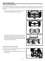
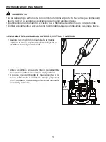
• Install the new scraper bar and fasten it securely to 

the snow thrower with the screws.

• Open the left side plate by removing six screws. 

• Use your right hand to turn the rib side of the belt 

up and pull upwards while turning the auger pulley 

counterclockwise with your left hand. The belt can 

be easily removed from the pulley.

• Put the belt on the drive pulley first and then place 

the belt at the lower end of the auger pulley.

3. REPLACING THE BELT

The screws that secure the scraper bar

Belt

Auger pulley

Drive pulley

Summary of Contents for 1314197

Page 1: ...TRIC SNOW THROWER ATTACH YOUR RECEIPT HERE Questions problems missing parts Before returning to your retailer call our customer service department at 1 888 3KOBALT 1 888 356 2258 8 a m 8 p m EST Monday Friday Serial Number Purchase Date Español p 21 ...

Page 2: ...11 Operating tips 14 Care and Maintenance 15 Troubleshooting 18 Warranty 19 Replacement Parts List 20 SPECIFICATIONS Rated Voltage 120 V 60 Hz Power 15 A No load speed 1800 rpm 10 Working width 21 in Depth of Snow Cut 12 in Wheels 8 in Discharge distance Up to 26 ft Weight 33 85 lbs Item Temperature Snow Thrower Storage Temperature Range 4 F 20 C 158 F 70 C Snow Thrower Operation Temperature Range...

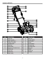
Page 3: ...witch box G Upper handle H Extension cord restraint hook I Handle locks J Power cord K Handle knob L Middle handle PART DESCRIPTION M Cable clip N Auxiliary handle O Lower handle P Wheels Q Chute deflector R Deflector knob S Discharge chute T Side cover U Impeller V Scraper bar W LED light A B E G C D F H I J K M N O P T U V W R Q L S ...

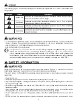
Page 4: ... manual before using this product Eye Protection Always wear eye protection with side shields marked to comply with ANSI Z87 1 Safety Alert Precautions that involve your safety Hand and Feet Keep hands and feet away Safe Distance Keep bystanders a safe distance from the machine Stop the Machine Stop the motor and disconnect the power supply before leaving the machine Moving Parts Stay away from mo...

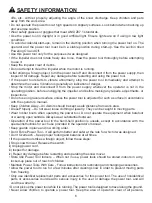
Page 5: ...er tool near glass enclosures automobiles trucks window wells drop Read and understand all instructions before using this product Failure to follow all instructions listed below may result in electric shock fire and or serious personal injury The term power tool in all of the warnings listed below refers to your mains operated corded power tool The operation of any power tool can result in foreign...

Page 6: ...s adjusted for such a surface in accordance with the operator s manual Keep Children Away All visitors should be kept a safe distance from work area Dress Properly Do not wear loose clothing or jewelry They can be caught in moving parts Wear rubber boots when operating the power tool Do not operate the equipment when barefoot or wearing open sandals Always wear substantial footwear Operation of th...

Page 7: ...uge A W G 14 12 particularly small children and pets Thoroughly inspect the area where the equipment is to be used and remove all stones sticks wires bones and other foreign objects Stop the blade s when crossing gravel drives walks or roads Read the operating and service instruction manual carefully Be thoroughly familiar with the controls and the proper use of the equipment Prevent unintentional...

Page 8: ... missing or damaged do not attempt to assemble the product Estimated Assembly Time 10 minutes Verify that the power tool is secure while transporting Store the power tool in a dry area that will prevent unauthorized use or damage Keep out of the reach of children Keep handles dry clean and free of debris Clean the power tool after each use Refer to the Maintenance Section in this manual for more i...

Page 9: ...s or accessories not recommended can result in serious personal injury Secure the connection of the middle handle assembly to the upper handle by fastening the handle locks on each side Align the holes in the bottom of the middle handle assembly with those in the lower handle Secure the middle handle assembly to the lower handle using 2 handle knobs and 2 square J bolts Install the knobs on the in...

Page 10: ...g the washer between the deflector and the chute Secure the carriage bolts and knobs Make sure the knobs are tightened Turn the crank knob clockwise to ensure the discharge chute and deflector are in position Chute deflector Washer Deflector knob Discharge chute Carriage bolt Deflector knob Washer Carriage bolt ...

Page 11: ... electrical cord If the cord is damaged do not use the snow thrower Replace or repair the damaged cord immediately NOTE Before using this machine make sure that the power source you will use complies with the specifications detailed in this manual Before inserting the plug into the socket verify that the snow thrower s impeller and rubber plates are firmly secured and that the rubber plates are fa...

Page 12: ...er The extension cord female end should be likewise polarized so that the extension cord fits snugly into the appliance plug To utilize the LED light for nighttime snow removal activate the LED light switch NOTE After you have finished using your snow thrower remember to turn OFF the LED light switch The impeller starts rotating immediately after the snow thrower is switched on Keep hands and feet...

Page 13: ...re that the chute deflector snaps and locks completely onto the discharge chute An opening between the discharge chute and the chute deflector may allow foreign objects to be picked up by the snow thrower and thrown in the direction of the operator causing serious boldly injury Always orient the discharge chute in the opposite direction from where you bystanders surrounding vehicles or windows are...

Page 14: ... move in the same direction as the wind so that the snow is not thrown against the wind and thus back onto you and on the just cleared path Do not push the snow thrower with excessive force You should push the machine gently and at a consistent speed in accordance with the unit s throw rate Some parts of the snow thrower may freeze under extreme temperature conditions Do not attempt to operate the...

Page 15: ... the worn impeller by removing the sets of nuts bolts and washers used to secure it Install the first replacement impeller and insert the appropriate bolt into the corresponding holes on each part of the impeller Make sure the lock nuts are firmly secured to the bolts Install the other impeller in the same manner Remove the screws that secure the scraper to the snow thrower CARE AND MAINTENANCE 1 ...

Page 16: ...g position Install the new scraper bar and fasten it securely to the snow thrower with the screws Open the left side plate by removing six screws Use your right hand to turn the rib side of the belt up and pull upwards while turning the auger pulley counterclockwise with your left hand The belt can be easily removed from the pulley Put the belt on the drive pulley first and then place the belt at ...
Page 17: ...cket turn the pulley clockwise to remove Follow directions in reverse to install the new pulley Use your right hand to press the belt with the ribbed side down While holding the belt down with your right hand use your left hand to turn the auger forward so that the auger pulley rotates in a clockwise direction The belt will be gradually pushed down onto the pulley When the belt is seated on the pu...

Page 18: ...rvicing requires extreme care and knowledge and should be performed only by a qualified service technician For service it is suggested you return the product to your nearest AUTHORIZED SERVICE CENTER for repair When servicing use only identical replacement parts If you still have questions or an unresolved issue after going through this troubleshooting guide or just want to speak to a Kobalt produ...

Page 19: ...to the place of purchase for a free replacement or refund or call 1 888 356 2258 for warranty service This warranty is void if defects in materials or workmanship or damages result from repairs or alterations which have been made or attempted by others or the unauthorized use of nonconforming parts the damage is due to normal wear damage is due to abuse including overloading of the tool beyond cap...

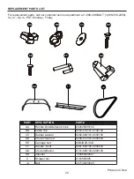
Page 20: ...Handle knob Deflector knob 202028000132 BB Cable clip 8343 515101 0100130 CC Rubber washer 8202 660101 0000130 DD Chute crank rod 8206 517001 0000030 EE Carriage bolt 8SBJD08 30D FF Square J bolt 8087 660105 0000030 GG Chute deflector 8101 660103 0000130 HH Impeller 199069000027 II Scraper bar 8181660905 JJ Belt 207130200005 HH I I JJ AA BB CC DD GG EE FF Printed in China ...

Page 21: ...BLE ADJUNTE SU RECIBO AQUÍ Preguntas problemas piezas faltantes Antes de volver a la tienda llame a nuestro Departamento de Servicio al Cliente al 1 888 3KOBALT 1 888 356 2258 de lunes a viernes de 8 a m a 8 p m hora estándar del Este Número de serie Fecha de compra Español p 21 ...

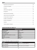
Page 22: ...nimiento 35 Solución de problemas 38 Garantía 39 Lista de piezas de repuesto 40 ESPECIFICACIONES Rango de voltaje 120 V 60 Hz Alimentación 15 A Velocidad sin carga 1800 rpm 10 Ancho de trabajo 53 34 cm Profundidad de penetración en la nieve 30 48 cm Ruedas 20 32 cm Distancia de descarga Hasta 7 92 m Peso 15 35 kg Artículo Temperatura Rango de temperatura de almacenamiento del equipo quitanieve 20 ...

Page 23: ...G Manija superior H Gancho de contención de la extensión eléctrica I Trabas de manija J Cable de alimentación K Perilla de la manija L Manija central PIEZA DESCRIPCIÓN M Sujetador del cable N Manija auxiliar O Manija inferior P Ruedas Q Deflector del conducto R Perilla del deflector S Conducto de descarga T Cubierta lateral U Propulsor V Barra raspadora W Luz LED A B E G C D F H I J K M N O P T U ...

Page 24: ...Lentes de protección Siempre use lentes de protección lateral que cumplan con la norma ANSI Z87 1 Alerta de seguridad Precauciones que involucran su seguridad Mano y pies Mantenga las manos y los pies alejados Distancia segura Mantenga a los espectadores a una distancia segura de la máquina Detenga la máquina Detenga el motor y desconecte el suministro de electricidad antes de dejar la máquina Pie...

Page 25: ...sin ajustar adecuadamente el ángulo de la descarga de nieve Mantenga a niños y mascotas alejados del área de trabajo Lea y comprenda todas las instrucciones antes de usar este producto Si no se siguen todas las instrucciones detalladas a continuación existe la posibilidad de una descarga eléctrica un incendio y o lesiones graves a la persona El término herramienta eléctrica que aparece en todas la...

Page 26: ...os alejados todas las visitas deben mantenerse a una distancia segura del área de trabajo Use ropa adecuada no use ropa holgada ni joyas Pueden quedar atrapadas en las piezas móviles Use botas de goma cuando utilice la herramienta eléctrica No use el equipo estando descalzo o al usar sandalias abiertas Siempre use un calzado adecuado El funcionamiento de la herramienta eléctrica en la posición de ...

Page 27: ...licen una herramienta eléctrica Mantenga el área de operación libre de cualquier persona en especial niños pequeños y mascotas Inspeccione minuciosamente el área donde se utilizará la herramienta y retire todas las piedras las varillas los cables los huesos y cualquier otro objeto extraño que encuentre Detenga las cuchillas cuando cruce entradas caminos o carreteras con gravilla Lea cuidadosamente...

Page 28: ...ue que la herramienta eléctrica esté segura durante el traslado Almacene la herramienta eléctrica en un lugar seco para evitar el uso no autorizado o daños Mantenga alejado del alcance de los niños Mantenga las manijas secas limpias y libres de residuos Limpie la herramienta eléctrica después de cada uso Para obtener más información consulte la sección de Mantenimiento de este manual Si las etique...

Page 29: ... puede sufrir lesiones personales graves Asegure la conexión del ensamble de la manija central a la manija superior mediante la fijación de las trabas de manija a cada lado Alinee los orificios en la parte inferior del ensamble de la manija central con los de la manija inferior Asegure el ensamble de la manija central a la manija inferior con 2 perillas de manija y 2 pernos en J cuadrados Instale ...

Page 30: ...os pernos con cabeza de hongo y las perillas Asegúrese de que las perillas estén apretadas Gire la manivela en dirección de las manecillas del reloj para asegurarse de que el conducto de descarga y el deflector estén en su posición Deflector del conducto Arandela Perilla del deflector Conducto de descarga Perno con cabeza de hongo Perilla del deflector Arandela Perno con cabeza de hongo ...

Page 31: ... use el equipo quitanieve si el cable está dañado Repare o reemplace inmediatamente el cable dañado NOTA antes de utilizar esta máquina asegúrese de que la fuente de alimentación que va a utilizar cumple con las especificaciones detalladas en este manual Antes de insertar el enchufe en el conector compruebe que el impulsor del equipo quitanieve y las placas de goma estén bien fijadas y que las pla...

Page 32: ...polarización para que la extensión eléctrica encaje perfectamente en el enchufe del electrodoméstico Para utilizar la luz LED para quitar nieve durante la noche active el interruptor de la luz LED NOTA después de que haya terminado de usar el equipo quitanieve recuerde apagar el interruptor de la luz LED El impulsor comienza a girar inmediatamente después de que se enciende el equipo quitanieve Ma...

Page 33: ...tamente en el conducto de descarga Una abertura entre el conducto de descarga y el deflector del conducto puede permitir que el equipo quitanieve recoja objetos extraños y los arroje en la dirección del operador lo que puede causar lesiones corporales graves Siempre oriente el conducto de descarga en la dirección opuesta al lugar donde se encuentra usted los transeúntes los vehículos circundantes ...

Page 34: ...n la misma dirección que el viento para que no se arroje nieve contra el viento y por lo tanto de regreso hacia usted y sobre el camino recién despejado No empuje el equipo quitanieve con fuerza excesiva Debe empujar la máquina suavemente y a una velocidad constante de acuerdo con la tasa de proyección de la unidad Algunas piezas del quitanieve pueden congelarse en condiciones de temperaturas extr...

Page 35: ...ado mediante la remoción de los juegos de tuercas pernos y arandelas utilizados para fijarlo Instale el primer impulsor de reemplazo e inserte el perno apropiado en los orificios correspondientes en cada parte del impulsor Asegúrese de que las contratuercas estén firmemente fijadas a los pernos Instale el otro impulsor de la misma manera Retire los tornillos que fijan el raspador al equipo quitani...

Page 36: ...emente al equipo quitanieve con los tornillos Abra la placa lateral izquierda mediante la extracción de seis tornillos Use su mano derecha para girar el lado de la pestaña de la correa hacia arriba y jale hacia arriba mientras gira la polea de la barrena en dirección contraria a las manecillas del reloj con su mano izquierda La correa se puede quitar fácilmente de la polea Primero coloque la corre...

Page 37: ...en dirección de las manecillas del reloj para extraerla Siga las instrucciones en orden inverso para instalar la nueva polea Use su mano derecha para presionar la correa con el lado estriado hacia abajo Mientras sujeta la correa con la mano derecha gire la barrena hacia delante con la mano izquierda para que la polea de la barrena gire en dirección de las manecillas del reloj La correa se empujará...

Page 38: ... y conocimiento y solo un técnico de servicio calificado debe realizarlo Para realizar el mantenimiento le recomendamos llevar el producto al CENTRO DE SERVICIO AUTORIZADO más cercano para su reparación Al realizar mantenimiento utilice solo piezas de repuesto idénticas a las de fabricación Si todavía tiene preguntas o un problema no resuelto después de leer esta guía de solución de problemas o si...

Page 39: ...emplazo o reembolso sin cargo o llame al 1 888 356 2258 para obtener el servicio de garantía Esta garantía es nula si los defectos en los materiales o la mano de obra o los daños han sido causados por reparaciones o modificaciones hechas o que se hayan intentado hacer por parte de terceros o el uso no autorizado de piezas incompatibles el daño es debido al desgaste normal el daño es debido al abus...

Page 40: ...e la manija perilla del deflector 202028000132 BB Sujetador del cable 8343 515101 0100130 CC Arandela de goma 8202 660101 0000130 DD Varilla de la manivela del conducto 8206 517001 0000030 EE Perno con cabeza de hongo 8SBJD08 30D FF Perno en J cuadrado 8087 660105 0000030 GG Deflector del conducto 8101 660103 0000130 HH Impulsor 199069000027 II Barra raspadora 8181660905 JJ Correa 207130200005 HH ...

Reviews: