


71
1
2
: There is an unknown satellite (when the NID lock is used for searching)
1
3
: Searching fail (clear if in normal state)
1
4
: No gyro input (refers to a communication error)(clear if in normal state)
1
5
: PCU DSP flash writing error
1
6
: PCU DSP EEPROM writing error
1
7
: Not used
1
8
: Not used
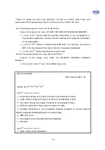
0x FF
(3)
=1
8
1
7
1
6
1
5
1
4
1
3
1
2
1
1
1
1
: Not used
1
2
: Not used
1
3
: Not used
1
4
: Not used
1
5
: Not used
1
6
: Not used
1
7
: Not used
1
8
: Not used
0x FF
(4)
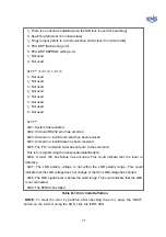
0x01: System has restarted
0x02: Unknown RS232 error has occurred
0x03: Unknown or invalid command has been received
0x04: Unknown or invalid data has been received.
0x05: The 'TS:' command must be sent prior to the command.
This is for programming the transponder/satellite data.
0x06: A tuner I2C bus failure has occurred. This could indicate that the tuner is
defective.
0x07: The LNB polarity voltage is not within the LNB polarity range. This could
indicate that the LNB voltage does not change or that the LNB voltage has shorted.
0x08: The LNB signal level is below the valid range. This could indicate that the LNB
is not connected.
0x09: The E2Ram has failed
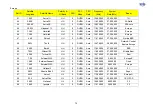
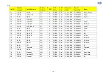
Table B-1 Error Code Definition
NOTE
: To clear the error by perforce after checking the error, press the ‘NEXT’
button on the ACU. If using the SCS, click the ‘ERR’ LED.
Summary of Contents for SUPERTRACK S4
Page 7: ...3 Figure 2 2 Best Location II Figure 2 3 Antenna Blockages ...
Page 11: ...7 Figure 2 7 Tighten the nuts from below ...
Page 13: ...9 Fixed Screws for Azimuth Figure 2 10 Fixed Screws for Azimuth ...
Page 28: ...24 Figure 3 3 Antenna Control Unit Back Panel ...
Page 45: ...41 Connection Staus Antenna Current State Figure 4 3 Connection Status S4 with PC ...
Page 48: ...44 Figure 4 6 Satellite List Update Step 2 ...
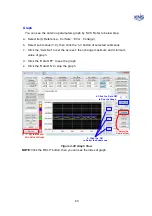
Page 56: ...52 C N You can see the graph of C N on Antenna State Graph of C N Figure 4 13 C N Graph ...
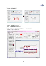
Page 71: ...67 Click the SAVE to save to PCU Click to Save ...
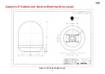
Page 81: ...77 Appendix E Radome and Antenna Mounting Holes Layout Figure E 1 S4 Plastic Radome Layout ...