


57
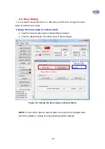
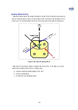
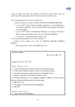
c. Change the level and cross tilt offset to place the bubble of bubble inclinometer
is in center
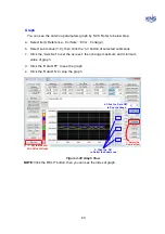
d. Click the ‘Tilt Offset’ to upload to PCU.
1. Change the value
2. Click to upload
Figure 4-18 Edit Tilt Offset
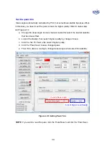
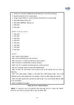
NOTE
: Click the ‘Command’ button after input the ‘Ibd’ in below box of ‘Command’ is
same function click the ‘Tilt Offset’.
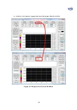
Figure 4-19 Request Current Tilt Offset Using ‘Ibd’ Command
Summary of Contents for SUPERTRACK S4
Page 7: ...3 Figure 2 2 Best Location II Figure 2 3 Antenna Blockages ...
Page 11: ...7 Figure 2 7 Tighten the nuts from below ...
Page 13: ...9 Fixed Screws for Azimuth Figure 2 10 Fixed Screws for Azimuth ...
Page 28: ...24 Figure 3 3 Antenna Control Unit Back Panel ...
Page 45: ...41 Connection Staus Antenna Current State Figure 4 3 Connection Status S4 with PC ...
Page 48: ...44 Figure 4 6 Satellite List Update Step 2 ...
Page 56: ...52 C N You can see the graph of C N on Antenna State Graph of C N Figure 4 13 C N Graph ...
Page 71: ...67 Click the SAVE to save to PCU Click to Save ...
Page 81: ...77 Appendix E Radome and Antenna Mounting Holes Layout Figure E 1 S4 Plastic Radome Layout ...