


12
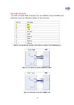
Gyro Cable Connection
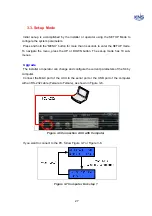
The cable connection differs according to the type of NMEA. Connect the NMEA port
with the ship’s gyro, as indicated in Figures 2-14 and 2-15 below.
Pin No.
Pin Name
1
RX-
2
RX+
3 TXD
4 DC
24V
5 GND
6 Dummy
7 GND
8 Dummy
9 Dummy
Table 2-1 Using the pin number of the ACU Connector for the NMEA type
Figure 2-14 Cable Connection NMEA 422/485
Figure 2-15 Cable Connection NMEA 232
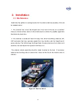
Summary of Contents for SUPERTRACK S4
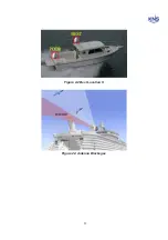
Page 7: ...3 Figure 2 2 Best Location II Figure 2 3 Antenna Blockages ...
Page 11: ...7 Figure 2 7 Tighten the nuts from below ...
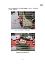
Page 13: ...9 Fixed Screws for Azimuth Figure 2 10 Fixed Screws for Azimuth ...
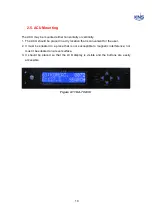
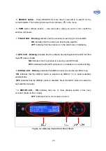
Page 28: ...24 Figure 3 3 Antenna Control Unit Back Panel ...
Page 45: ...41 Connection Staus Antenna Current State Figure 4 3 Connection Status S4 with PC ...
Page 48: ...44 Figure 4 6 Satellite List Update Step 2 ...
Page 56: ...52 C N You can see the graph of C N on Antenna State Graph of C N Figure 4 13 C N Graph ...
Page 71: ...67 Click the SAVE to save to PCU Click to Save ...
Page 81: ...77 Appendix E Radome and Antenna Mounting Holes Layout Figure E 1 S4 Plastic Radome Layout ...