background image

0901177 Rev: A  (10/15) 

Page 5 of 12 

ELECTRICAL 

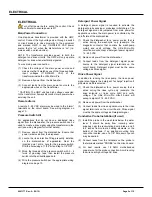
       Turn off all power before wiring the control. Check 
with a voltmeter to ensure power is off. 

Main Power Connection 

One step-down transformer is provided with the UMP 
control. Connect the high voltage side, through a switch 
or circuit breaker in close proximity to the equipment 
and marked UMP, to any 115/208/230 VAC power 
source that is “on” when the dishmachine is “on” (i.e. 
mains switch on dishmachine). 

NOTE: The transformer provides power to both the 
detergent and rinse circuits. The UMP will only operate 
detergent or rinse when electrically signaled. 

To wire main power connection: 

(1)  Check the voltage of the main power source and 

make sure that it matches one of the three available 
input voltages (115/208/230 VAC) of the 
transformer inside the Ultra Micro-Pro. 

(2)  Remove all power from the dishwasher. 

(3)  Connect leads from the main power source to the 

appropriate wires on the transformer. 

* CAUTION: The UMP unit has high voltage connected 
to the transformer. Always disconnect main power when 
servicing the unit. 

Remote Alarm 

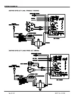
A remote 3 - 28 VDC alarm may be wired to the “alarm” 
terminals on the circuit board. See wiring diagram on 
page 10. 

Pressure Switch Kit 

For applications that do not have a dedicated rinse 
signal from the dishwasher, the pressure switch can be 
used to create a rinse signal using the transformer in the 
unit (see wiring diagram for further details). 

(1)  Remove power from the dishmachine. Ensure that 

power is removed from the dispenser. 

(2)  Locate the rinse injection fitting presently installed 

on the dishmachine (if applicable). Near the 
injection point, drill a hole for the pressure switch. 
Drill the hole using a 11/32" bit and tap to 1/8" NPT. 

(3)  Wrap the threads of the pressure switch with 3 - 4 

turns of plumbing tape, then install the pressure 
switch into the drilled/tapped hole. 

(4)  Wire the pressure switch per the appropriate wiring 

diagram on page 10. 

Detergent Power Signal 

A detergent power signal is required to activate the 
detergent probe sensing or probeless initial charge. The 
detergent signal can be jumpered from main power for 
applications where the main power is controlled by the 
on/off state of the dishmachine. 

(1)  Check the dishwasher for a power source that is 

active during the washcycle only (example: the 
magnetic contactor that controls the washpump 
motor) and verify voltage. The Ultra Micro-Pro 
circuit board will accept a detergent power signal of 
14 - 240 VAC. 

(2)  Remove all power from the dishwasher. 

(3)  Connect leads from the detergent signal power 

source to the detergent signal terminals on the 
circuit board. Detergent signal must be the same 
voltage as Rinse signal. 

Rinse Power Signal 

In addition to running the rinse pump, the rinse power 
signal also triggers the detergent “recharge” injection if 
probeless mode is selected


(1)  Check the dishwasher for a power source that is 

active during the rinse cycle only (example: the 
rinse solenoid or rinse cycle light) and verify 
voltage. The Ultra Micro-Pro circuit board will 
accept a signal of 14 - 240 VAC. 

(2)  Remove all power from the dishwasher. 

(3)  Connect leads from rinse signal source to the rinse 

signal terminals on the circuit board. Rinse signal 
must be the same voltage as Detergent signal. 

Conductive Probe Installation (if used) 

(1)  Install the probe in the wash tank below the water 

level. It should be away from incoming water 
supplies, near the recirculating pump intake, and 3 
to 4 inches from corners, heating elements, or the 
bottom of the tank. If an existing mounting hole 
cannot be located, use of a 7/8" hole saw or punch 
may be desired. 

(2)  Connect leads from the terminals on the probe to 

the terminals marked “PROBE” on the circuit board. 

(3) For best results, use 18 AWG multi-stranded 

copper wire for the probe connection. Avoid running 
the wire near high voltage AC lines. 

ELECTRICAL


Summary of Contents for UMP Hospitality

Page 1: ...tality Instruction Manual TABLE OF CONTENTS Settings Guide 2 Installation Diagram 3 Dimensions 3 Accessory Kit 3 Installation 4 Electrical 5 Operation 6 Programming 7 Parts Diagram 9 Wiring Diagram 10 Warranty Information 12 Knight Locations 12 ...

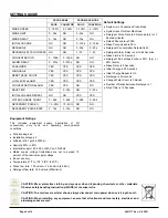
Page 2: ...0 999 0 999 0 999 DETERGENT PULSE 10 90 10 90 NO NO DETERGENT PULSE RATE 3 15s 3 15s NO NO SETTINGS GUIDE Default Settings System is in Conductive Probe Mode System is set for Door Machines Detergent Pulse Rate is 5 Seconds dry or 3 Seconds liquid Default Password is 0000 Rinse Pump Speed is 50 Detergent Concentration Setpoint is 25 Detergent Alarm Delay is set to 64 Seconds Rinse Limit is 30 Seco...

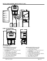
Page 3: ...uction Manual 0901177 INSTALLATION DIAGRAM UMP HOSPITALITY 200L MAIN UNIT DIMENSIONS UMP Hospitality 200D Accessory Kit 1 1 4 Poly tubing 20 ft 7028109 2 1 x Pick up tube 7020180 3 2 x Expansion screw includes wall anchor and screw 7600121 4 1 x Check Valve 1 4 tube 7901350 5 1 x Fitting Bulkhead Ell 7023342 6 1 x Probe includes gasket nut lock 7005190 7 2 x Tie Wrap 3 5 in long 0300121 8 Tube T 5...

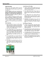
Page 4: ... and the pickup tube provided Be sure to draw tubing through the end of the pickup tube 4 Hand tighten the compression nuts on both the rinse fitting and pickup tube Plastic ties can be used to cinch around the connections where the poly tubing is inserted into the pump s squeeze tube Liquid Detergent Plumbing 1 Install the provided bulkhead fitting through a wall of the wash tank above water leve...

Page 5: ...ch into the drilled tapped hole 4 Wire the pressure switch per the appropriate wiring diagram on page 10 Detergent Power Signal A detergent power signal is required to activate the detergent probe sensing or probeless initial charge The detergent signal can be jumpered from main power for applications where the main power is controlled by the on off state of the dishmachine 1 Check the dishwasher ...

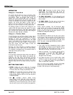
Page 6: ...un and program modes Enter also advances through programming menus SCROLL The scroll button moves the position of the cursor where number changes are done The scroll button toggles between choices in menus that have selectable settings UP Increases numeric values during programming The UP button also acts as rinse prime during operation To prime the rinse pump hold down SCROLL and UP at the same t...

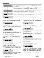
Page 7: ... 0 to 30 Press ENTER to continue RACK TIME 000 This setting tells the system when to begin pulse feeding specifically at what percent of the detergent concentration you have just set in the previous display 85 is the default value for liquid detergent 50 is the default value for dry detergent Press SCROLL to select the digit you wish to change then use to change the number the range is 10 to 90 Pr...

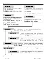
Page 8: ...number the speed of the pump will change as the number is changed When finished press ENTER to continue RINSE SPEED 050 This setting will only appear if using door mode This feature will stop the rinse pump after XX seconds of continuous rinse signal conserving rinse agent on door type dishmachines that fill through the rinse valve The range is from 0 to 30 seconds Press SCROLL to select the digit...

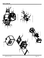
Page 9: ...0901177 Rev A 10 15 Page 9 of 12 PARTS DIAGRAM ...

Page 10: ...Page 10 of 12 0901177 Rev A 10 15 UMP HOSPITALITY 200L PRODUCT WIRING UMP HOSPITALITY 200D PRODUCT WIRING WIRING DIAGRAM ...

Page 11: ...0901177 Rev A 10 15 Page 11 of 12 NOTES ...

Page 12: ...ctive upon factory authorized inspection Bearings and pump seals or rubber and synthetic rubber parts such as O rings diaphragms squeeze tubing and gaskets are considered expendable and are not covered under warranty Warranty does not cover liability resulting from performance of this equipment nor the labor to replace this equipment Product abuse or misuse voids warranty FOOTNOTE The information ...

Reviews: