background image

26

4  

Gas connections 

Outdoor boilers are typically shipped ready to fire on natural gas.  Check boiler rating plate to determine 
which fuel the boiler is set for.  If set to natural gas, it may be converted to LP by installing an orifice (see page 
11).  In order to operate on LP gas, an orifice MUST BE installed.  Failure to comply could result in severe 
personal injury, death, or substantial property damage.

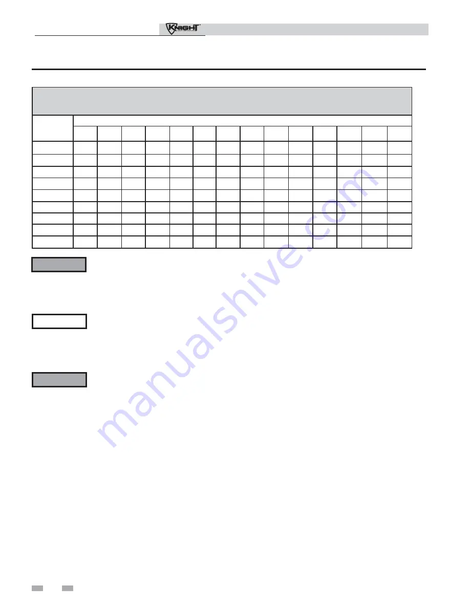
Table 4A Natural Gas Pipe Size Chart

The gas piping must be sized for the proper flow and length 
of pipe, to avoid excessive pressure drop.  Both the gas meter 
and the gas regulator must be properly sized for the total gas 
load.  

If you experience a pressure drop greater than 1 inch w.c., 
the meter, regulator, or gas line is undersized or in need of 
service.  Perform the steps below when checking inlet gas 
supply:

1.  Turn the main power switch to the “OFF” position.

2.  Shut off gas supply at the manual gas valve in the gas 
 

piping to the appliance.  

 WARNING

3.  Loosen the set screw one (1) full turn from inside the 
 

pressure tap on top of the gas valve.  Place the tubing of 


the manometer over the tap once the set screw is 


loosened as shown in FIG. 4-3.

4.  Slowly turn on the gas supply at the field installed 
 

manual gas valve.

5.  Turn the power switch to the “ON” position.

6.  Adjust the temperature set point on the control panel of 
 

the SMART SYSTEM control module to call for heat.

7.  Observe the gas supply pressure as the burner fires at 
 

100% of rated input.  Percent of burner input will be 


displayed on the control panel.

8.  Ensure inlet pressure is within specified range. 


Minimum and maximum gas supply pressures are 


specified in this section of the manual.

9.  If gas supply pressure is within normal range and no 
 

adjustments are needed, proceed on to Step 11.  

10.  If the gas pressure is out of range, contact the gas utility, 
 

gas supplier, qualified installer or service agency to 


determine the necessary steps to provide proper gas 


pressure to the control.

11.  Turn the power switch to the “OFF” position.

12.  Shut off the gas supply at the manual gas valve in the gas 
 

piping to the appliance.  

13.  Remove the manometer from the pressure tap on top of 
 

the gas valve.  Re-tighten the set screw inside the pressure 

 tap. 

Check inlet gas supply

 NOTICE

CSA or UL listed flexible gas connections 
are acceptable, but you must exercise 
caution to ensure that the line has adequate 
capacity to allow your boiler to fire at full 
rate.  Consult with local codes for proper 
installation or service procedures.

DO NOT adjust gas valve outlet pressure.  
The gas valve is factory-set for the correct 
outlet pressure.  This setting is suitable 
for natural gas and propane, requiring 
no field adjustment.  Attempting to 
alter the gas valve outlet pressure could 
result in damage to the valve, causing 
potential severe personal injury, death, or 
substantial property damage.

 WARNING


Outdoor Knight Boiler Installation & Operation Manual

Capacity of Schedule 40 Metallic Pipe in Cubic Feet of Natural Gas Per Hour

(based on .60 specific gravity, 0.30" w.c. pressure drop)

Pipe

Size

(Inches)

Length of Pipe in Straight Feet

10

20

30

40

50

60

70

80

90

100

125

150

175

200

1/2

131

90

72

62

55

N/A

N/A

N/A

N/A

N/A

N/A

N/A

N/A

N/A

3/4

273

188

151

129

114

104

95

89

83

79

70

63

58

N/A

1

514

353

284

243

215

195

179

167

157

148

131

119

109

102

1 1/4

1,060

726

583

499

442

400

368

343

322

304

269

244

224

209

1 1/2

1,580

1,090

873

747

662

600

552

514

482

455

403

366

336

313

2

3,050

2,090

1,680

1,440 1,280 1,160 1,060

989

928

877

777

704

648

602

2 1/2

4,860

3,340

2,680

2,290 2,030 1,840 1,690

1,580

1,480

1,400

1,240

1,120

1,030

960

3

8,580

5,900

4,740

4,050 3,590 3,260 3,000

2,790

2,610

2,470

2,190

1,980

1,820

1,700

4

17,500 12,000 9,660

8,270 7,330 6,640 6,110

5,680

5,330

5,040

4,460

4,050

3,720

3,460

Summary of Contents for 151-286

Page 1: ...ified heating installer service technician Read all instructions including this manual and the Outdoor Knight Boiler Service Manual before installing Perform steps in the order given Failure to comply could result in severe personal injury death or substantial property damage WARNING Save this manual for future reference ...

Page 2: ...OILER LOCATION Provide Clearances 9 Corrosive Contaminants and Sources 9 2 PREPARE BOILER Remove Boiler from Wood Pallet 10 Gas Conversions 10 11 Leveling the Boiler 11 3 HYDRONIC PIPING System Water Piping Methods 12 Low Water Cutoff Device 12 Chilled Water System 12 Freeze Protection 12 General Piping Information 12 Relief Valve T P Installation 13 Near Boiler Piping Components 13 14 Near Boiler...

Page 3: ...NG NOTICE WARNING WARNING When servicing boiler To avoid electric shock disconnect electrical supply before performing maintenance To avoid severe burns allow boiler to cool before performing maintenance Boiler operation Do not block flow of combustion or ventilation air to the boiler Should overheating occur or gas supply fail to shut off do not turn off or disconnect electrical supply to circula...

Page 4: ...The SMART SYSTEM Control responds to internal and external signals and controls the blower gas valve and pumps to meet the heating demand 17 Manual air vent Designed to remove trapped air from the heat exchanger coils 18 High voltage junction box The junction box contains the connection points for the line voltage power and all pumps 19 Boiler drain port Location from which the heat exchanger can ...

Page 5: ... Left Side inside unit Models 151 211 Right Side inside unit Models 151 211 The Outdoor Knight Boiler How it works continued Rear View Models 151 211 Models 151 211 4 5 36 7 35 2 26 18 20 16 34 3 1 17 IMG00368 Outdoor Knight Boiler Installation Operation Manual ...

Page 6: ...r How it works Model 286 Left Side inside unit Model 286 Right Side inside unit Model 286 Front View Model 286 Rear View Model 286 IMG00379 24 23 10 31 30 IMG00382 34 16 17 3 1 Outdoor Knight Boiler Installation Operation Manual ...

Page 7: ...4 for each 1 000 feet above sea level up to 4 500 feet 5 Ratings have been confirmed by the Hydronics Section of AHRI 6 Outdoor boilers temperature controls comply with the requirements of CSD 1 Section CW 400 requirements The manual reset high limit provided with the outdoor boiler is listed to UL353 Maximum allowed working pressure is located on the rating plate NOTICE Outdoor Knight Boiler AHRI...

Page 8: ...ical surface to prevent wind conditions from affecting performance The outdoor unit must not be installed in an area that is enclosed by walls or a fence that will block free wind movement around the unit Free movement of wind around the outdoor unit is required to carry away the flue products and provide combustion air The flue outlet combustion air inlet of an outdoor unit must not be installed ...

Page 9: ...mstances is the manufacturer to be held responsible for water damage in connection with this appliance or any of its components If flooding is possible elevate the boiler sufficiently to prevent water from reaching the boiler Outdoor vent air intake location The flue products discharged from the flue outlet on the outdoor vent may be very hot Avoid touching or other direct contact with the flue ga...

Page 10: ...he venturi FIG 2 3 3 Locate the propane orifice disk from the conversion kit bag Verify that the stamping on the orifice disk matches the boiler size see Table 2A Place the orifice into the black rubber grommet in the side of the gas valve and secure in the valve FIG 2 3 4 Reposition the gas valve against the venturi and replace the screws FIG 2 3 securing the valve to the venturi 2 Prepare boiler...

Page 11: ...ifice Figure 2 4 Leveling Legs on the Boiler Leveling the boiler 1 Set the boiler in place and check level a Adjust legs if necessary to level boiler see FIG 2 4 below WARNING After converting to LP check combustion per the Start up procedure in Section 7 of this manual Failure to check and verify combustion could result in severe personal injury death or substantial property damage LP Conversion ...

Page 12: ...al piping information Basic steps are listed in this section along with illustrations on the following pages FIG s 3 4 thru 3 10 which will guide you through the installation of the outdoor boiler reference FIG s 3 2A and 3 2B 1 Connect the system return marked Inlet 2 Connect the system supply marked Outlet 3 Install purge and balance valve or shutoff valve and drain on system return to purge air...

Page 13: ...MUST be sized per the pipe requirements listed in Table 3A Reducing the pipe size can restrict the flow rate through the boiler causing inadvertent high limit shutdowns and poor system performance Flow rates are based on 20 feet of piping 4 90 elbows and 2 fully ported ball valves 2 Boiler system circulating pump Field supplied The boiler circulating pump should be based on 20 feet 6 m of piping 4...

Page 14: ...d to control and balance the space heating demand by switching between DHW and space heating WARNING The National Standard Plumbing Code and the Uniform Plumbing Code limit the pressure of the heat transfer fluid to less than the minimum working pressure of the potable water system up to 30 psi maximum Also the heat transfer fluid must be water or other non toxic fluid having a toxicity of Class 1...

Page 15: ...6 99F 0013 NRF 36 E7 286 21 12 1 1 4 UPS26 99F 0011 NRF 36 E7 Pumps listed in bold type are provided by the factory as the boiler circulation pump on standard altitude models NOTICE 35 F Temperature Rise Applications Model GPM FT HD Minimum Pipe Size Pump Grundfos TACO B G Armstrong 151 8 10 1 UPS15 58FC 008 0010 NRF 36 Astro 30 211 11 9 1 UPS15 58FC 0010 NRF 36 Astro 50 286 15 7 1 1 4 UP26 64F 00...

Page 16: ... 230V pump listed in the shaded area in Table 3B to the boiler high voltage terminal strip Variable speed pump setup Before operation ensure the following Pump is set for an input signal of 0 10Vdc by the dip switches on the pump control Pump is set for external signal control if applicable Pump is set for linear output if applicable If pump does not come equipped with a 0 10 Vdc input option an o...

Page 17: ...ER OUT ZONE CIRCULATORS TYPICAL FLOW CHECK VALVE TYPICAL BOILER CIRCULATOR SYSTEM SUPPLY SENSOR WHEN USED Y STRAINER RECOMMENDED MAY SUBSTITUTE LOW LOSS HEADER IMG00370 ZONE 3 ZONE 4 ZONE 1 Figure 3 4 Single Boiler Single Temperature Zoned with Circulators Please note that these illustrations are meant to show system piping concept only the installer is responsible for all equipment and detailing ...

Page 18: ...YSTEM SUPPLY SENSOR TEMPERATURE PRESSURE GAUGE DRAIN MAY SUBSTITUTE LOW LOSS HEADER Y STRAINER RECOMMENDED TYPICAL IMG00371 ZONE 3 ZONE 4 ZONE 1 Figure 3 5 Multiple Boilers Single Temperature Zoned with Circulators Please note that these illustrations are meant to show system piping concept only the installer is responsible for all equipment and detailing required by local codes Indoor tank shown ...

Page 19: ...UP WATER HOT WATER OUT BOILER CIRCULATOR BACKFLOW PREVENTER PRESSURE GAUGE EXPANSION TANK MIXING VALVES TYPICAL FLOW CHECK VALVE SYSTEM SUPPLY SENSOR DRAIN Y STRAINER RECOMMENDED MAY SUBSTITUTE LOW LOSS HEADER TEMPERATURE LOOP 1 TEMPERATURE LOOP 2 TEMPERATURE LOOP 3 NOT TO EXCEED 4 PIPE DIA OR MAX OF 12 APART PRESSURE REDUCING VALVE SHIELDED CABLE TO BOILER CONTROL WIRES TO LOOP SENSORS MULTI TEMP...

Page 20: ...F 12 APART BOILER IMG00373 120VAC TO PUMPS WIRES TO LOOP SENSORS SHIELDED CABLE TO BOILER CONTROL MULTI TEMP LOOP CONTROL OPTIONAL 24V SIGNAL TO MIXING VALVES Figure 3 7 Multiple Boilers Multiple Temperatures Model Number of Units 2 3 4 5 6 7 8 Required Pipe Sizes 151 2 2 2 1 2 2 1 2 3 3 3 1 2 211 2 2 1 2 3 3 3 1 2 4 4 286 2 1 2 2 1 2 3 3 1 2 3 1 2 4 5 Please note that these illustrations are mean...

Page 21: ...RE PRESSURE GAUGE PRESSURE RELIEF VALVE SHIELDED CABLE TO BOILER CONTROL 24V SIGNAL TO MIXING VALVES 120VAC TO PUMPS WIRES TO LOOP SENSORS MULTI TEMP TO LOOP CONTROL IMG00374 Figure 3 8 Multiple Boilers Multiple Temperatures with DHW Piped as a Zone Please note that these illustrations are meant to show system piping concept only the installer is responsible for all equipment and detailing require...

Page 22: ...SYSTEM CIRCULATOR DRAIN Y STRAINER RECOMMENDED TYPICAL MAY SUBSTITUTE LOW LOSS HEADER NOT TO EXCEED 4 PIPE DIA OR MAX OF 12 APART IMG00375 FLOW CHECK VALVE ZONE 2 ZONE 3 ZONE 4 Figure 3 9 Multiple Boilers Single Temperature Zoned with Valves Please note that these illustrations are meant to show system piping concept only the installer is responsible for all equipment and detailing required by loc...

Page 23: ...TEM CIRCULATOR NOT TO EXCEED 4 PIPE DIA OR MAX OF 12 APART Y STRAINER RECOMMENDED TYPICAL MAY SUBSTITUTE LOW LOSS HEADER HOT WATER OUT IMG00376 FLOW CHECK VALVE Figure 3 10 Multiple Boilers Non Zoned Primary Secondary Piping Please note that these illustrations are meant to show system piping concept only the installer is responsible for all equipment and detailing required by local codes Indoor t...

Page 24: ...ystem at test pressures equal to or less than 1 2 PSIG 3 5 kPa c The appliance and its gas connection must be leak tested before placing it in operation WARNING 6 Use pipe sealing compound compatible with propane gases Apply sparingly only to male threads of the pipe joints so that pipe dope does not block gas flow Failure to apply pipe sealing compound as detailed in this manual can result in sev...

Page 25: ...ator in supply line if inlet pressure can exceed 14 inches w c at any time Adjust lockup regulator for 14 inches w c maximum Propane Gas Pipe sizing for propane gas 1 Contact gas supplier to size pipes tanks and 100 lockup gas pressure regulator Propane Supply Pressure Requirements 1 Adjust propane supply regulator provided by the gas supplier for 14 inches w c maximum pressure 2 Pressure required...

Page 26: ... out of range contact the gas utility gas supplier qualified installer or service agency to determine the necessary steps to provide proper gas pressure to the control 11 Turn the power switch to the OFF position 12 Shut off the gas supply at the manual gas valve in the gas piping to the appliance 13 Remove the manometer from the pressure tap on top of the gas valve Re tighten the set screw inside...

Page 27: ...amic mode If an in line regulator is used it must be a minimum of 10 feet from the outdoor boiler It is very important that the gas line is properly purged by the gas supplier or utility company Failure to properly purge the lines or improper line sizing will result in ignition failure The problem is especially noticeable in NEW LP installations and also in empty tank situations This can also occu...

Page 28: ...olate with a relay Figure 5 1 Line Voltage Field Wiring Connections Label all wires prior to disconnection when servicing controls Wiring errors can cause improper and dangerous operation WARNING NOTICE CAUTION Low voltage connections 1 Route all low voltage wires through the knockouts in the rear of the boiler as shown in FIG 5 2 2 Connect low voltage wiring to low voltage connection board as sho...

Page 29: ...r 1 By installing a tank sensor the SMART SYSTEM control can perform the tank thermostat function The SMART SYSTEM control automatically detects the presence of this sensor and generates a DHW call for heat when the tank temperature drops 6 F 3 C below the tank set point and finishes the call for heat when the tank temperature reaches the tank set point 2 The tank sensor included with the Lochinva...

Page 30: ... off This can be used to turn on an alarm or signal a Building Management System that the boiler is down Wiring of the cascade When wiring the boilers for Cascade operation select one boiler as the Leader boiler The remaining boilers will be designated as Members See page 38 Configuration of the Cascade for a detailed explanation of this procedure Connect the system supply sensor and outdoor air s...

Page 31: ...OFF OUTDOOR SENSOR TANK SENSOR SHIELD SHIELD TO NEXT BOILER A B A B FROM PREVIOUS BOILER ROOM THERMOSTAT 1 ROOM THERMOSTAT 2 A B NOTE CONNECTION BOARD SPLIT FOR ILLUSTRATION PURPOSES WIRE AS NEEDED SYSTEM PUMP SPEED CONTROL BOILER PUMP IMG00127 Figure 5 3 Low Voltage Field Wiring Connections Outdoor Knight Boiler Installation Operation Manual ...

Page 32: ...aterials approved by the authority having jurisdiction In the absence of other authority PVC and CPVC pipe must comply with ASTM D1785 or D2845 Cement and primer must comply with ASME D2564 or F493 7 A condensate removal pump is required if the boiler is below the drain When installing a condensate pump select one approved for use with condensing boilers and furnaces The pump should have an overfl...

Page 33: ... will reduce boiler life Minerals can build up in the heat exchanger reducing heat transfer overheating the heat exchanger and causing heat exchanger failure Purge air from water system 1 Purge air from system a Connect a hose to the purge valve see purge drain valves in piping diagrams on pages 17 through 23 Route the hose to an area where water can drain and be seen b Close the boiler or system ...

Page 34: ...voltmeter across these two incoming wires Close each thermostat zone valve and relay in the external circuit one at a time and check the voltmeter reading across the incoming wires 3 There should NEVER be a voltage reading 4 If a voltage does occur under any condition check and correct the external wiring This is a common problem when using 3 wire zone valves 5 Once the external thermostat circuit...

Page 35: ...nual vents Air in the system will interfere with circulation and cause heat distribution problems and noise Check gas piping 1 Check around the boiler for gas odor following the procedure on page 24 of this manual connecting gas supply piping If you discover evidence of any gas leak shut down the boiler at once Find the leak source with a bubble test and repair immediately Do not start the boiler ...

Page 36: ...36 7 Start up Figure 7 2 Operating Instructions Outdoor Knight Boiler Installation Operation Manual ...

Page 37: ...ts down and registers an alarm Turn the manual shutoff switch to the ON position and reset the control 9 Turn the main power off to the boiler 10 Place the boiler back into normal operation Natural Gas Propane CO2 O2 CO2 O2 8 0 10 5 2 8 6 5 9 0 11 4 1 6 9 7 Start up continued Please note that the brackets denote screen status NOTICE 4 Place the boiler into the active position by pressing the RIGHT...

Page 38: ...oiler has been powered off for more than 4 hours Use the following procedure to set the clock 1 Press and hold the LEFT SELECT MENU key for at least 5 seconds 2 The display changes to read PASSWORD with four 4 zeros below it 3 Press the RIGHT SELECT SAVE key 4 The display will then show a menu with the time and date and temperature unit 5 Press the NAVIGATION dial twice 6 Turn the NAVIGATION dial ...

Page 39: ...he outdoor boiler can also be programmed to accept a call for heat from a 0 10V signal reference the Outdoor Knight Boiler Service Manual for a detailed explanation of this procedure DHW priority The SMART SYSTEM control allows the connection of a DHW thermostat or tank sensor to the low voltage connection board When a tank sensor is connected the DHW thermostat input is ignored When a boiler is p...

Page 40: ...7 days can be temporarily bypassed if desired Flame current support To prevent nuisance shutdowns when the boiler is firing at minimum rates the control will increase the firing rate when the flame signal drops too low Protection features Outlet temperature flue temperature and temperature rise limiting The outlet temperature is monitored by the boiler outlet temperature sensor When the outlet tem...

Page 41: ...ected If the outdoor sensor is not connected the target temperature is fixed at SH 1 3 set points An outdoor sensor fault will remain on the display screen until the outdoor sensor is reconnected High limit operations The outdoor boiler is equipped with adjustable automatic reset and manual reset high limits The automatic reset high limit has a maximum set point of 200 F and the manual reset high ...

Page 42: ...just its set point to the programmed DHW boiler set point and will adjust its firing rate to maintain this Once the DHW call has been satisfied the Leader control will place that boiler back into the Cascade sequence Switching of the boiler between DHW operation and SH operation when there is a call for both does not occur in Cascade Mode When DHW is programmed for Zone Mode connect the DHW thermo...

Page 43: ...the trial for ignition by firing the spark electrode and opening the gas valve 6 If flame is not detected after the sparking ends the control will perform a post purge then start another prepurge cycle and try to light the burner again The control will perform a total of 4 attempts before locking out 7 If flame is detected it holds the firing rate steady for a few seconds to let the flame stabiliz...

Page 44: ...re to the DHW boiler set point 9 If the boiler is not part of a Cascade and both the space heating and DHW calls for heat remain active long enough the boiler will switch back and forth between the two heating modes until one of them is satisfied 10 Once both calls for heat are satisfied the control will turn off the burner The blower will continue to run during the postpurge period 11 Any pumps t...

Page 45: ...taller Most parameters are available only to the installer accessible by entering the installer password see the Outdoor Knight Boiler Service Manual Saving parameters reference the Parameter Table in the Outdoor Knight Boiler Service Manual Please note that the brackets denote screen status NOTICE To save parameters and exit programming Press the RIGHT SELECT SAVE key and then press the RIGHT SEL...

Page 46: ...he combustion chamber and vent system of residual flue products SHUTDOWN The unit has been placed in the OFF position The controlled temperature has exceeded its set point and its offset BLOCKED The unit has detected a condition that has temporarily interrupted the current call for heat B Call for Heat Indicators Heat Loop Demand 1 has a call for heat Heat Loop Demand 2 has a call for heat Heat Lo...

Page 47: ...The speed of the combustion blower BOILER PUMP The status of the boiler pump output SYSTEM PUMP The status of the system pump output DHW PUMP The status of the DHW pump output BMS VOLTAGE The voltage received from a BMS system BLR PUMP OUTPUT The speed signal sent to a variable speed boiler pump in percent SYS PUMP INPUT The speed signal received from a variable speed system pump control RATE OUTP...

Page 48: ...n Turning the NAVIGATION dial will select the next or previous Status Screen Pressing the NAVIGATION dial will show the next fault NSB Night Setback trigger or ramp delay setting Pressing the NAVIGATION dial will select the setting indicated by the cursor Pressing the NAVIGATION dial will display the Set Points Screen Turning the NAVIGATION dial will move the cursor up or down Turning the NAVIGATI...

Page 49: ...s manual Flame inspection stable uniform Flame signal at least 10 microamps at high fire Clean the heat exchanger if flue temperature is more than 54 F above return water temperature If combustion or performance indicate need Clean heat exchanger Remove and clean burner using compressed air only Clean the blower wheel ANNUAL START UP Owner maintenance see the Outdoor Knight User s Information Manu...

Page 50: ...resent in the boiler intake air vicinity they must be removed Inspect boiler interior 1 Remove the front access cover and inspect the interior of the boiler 2 Vacuum any sediment from inside the boiler and components Remove any obstructions Clean condensate trap 1 Inspect the condensate drain line condensate PVC fittings and condensate trap 2 Remove the PVC cap retaining screw from the PVC cap FIG...

Page 51: ...LEAST ONCE EVERY THREE YEARS by a licensed plumbing contractor or authorized inspection agency to ensure that the product has not been affected by corrosive water conditions and to ensure that the valve and discharge line have not been altered or tampered with illegally Certain naturally occurring conditions may corrode the valve or its components over time rendering the valve inoperative Such con...

Page 52: ...limit controls if any and adjust if necessary Perform start up and checks 1 Start boiler and perform checks and tests specified in Section 7 Start up 2 Verify cold fill pressure is correct and that operating pressure does not go too high Check burner flame 1 Inspect flame through observation window 2 If the flame is unsatisfactory at either high fire or low fire turn off boiler and allow boiler to...

Page 53: ...assembly 11 Close isolation valves on piping to isolate boiler from system Attach a hose to the boiler drain and flush boiler thoroughly with clean water by using purging valves to allow water to flow through the water make up line to the boiler 12 Perform start up and check out procedures in the Check Flame and Combustion Section 7 Startup on pages 35 and 37 of this manual 13 Replace the access c...

Page 54: ...ACE S2 S1a S1b S3a S3b 21 22 26 27 23 24 30 31 32 33 35 36 37 38 39 40 41 42 43 44 3 4 1 2 ALARM CONTACTS M O D B U S 29 34 9 5 6 7 8 X2 2 NOTES 1 Where possible switches are shown without utilities gas water or electricity connected to the unit As such actual switch states may vary from those shown on diagrams depending upon whether utilities are connected or a fault condition is present 2 See wi...

Page 55: ...ge AWG and rated for a minimum of 105 C Exceptions Replacement high voltage spark lead and ribbon cables must be purchased from the factory Use of a non approved spark lead or ribbon cables can lead to operational problems which could result in non repairable damage to the integrated controller or other components 3 Actual connector block locations may vary from those shown on diagrams Refer to ac...

Page 56: ...ch below 32 F and Table 1A on page 8 ECO C11814 reflects edits made to place the check valves on the outlet side of the pump on all of the piping diagrams Revision E ECO C12763 revised the maximum CO2 and the minimum O2 R06021 on page 37 Revision F ECO C14411 reflects condensate trap changes R6594 changes made to Table 4A Gas Piping Chart on page 26 R6621 the addition of the corrosive contaminant ...

Reviews: