Installation and connection
Diaphragm Pump UN035_I EX
12
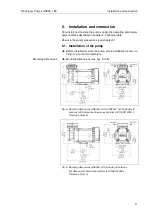
Fig. 7: Mounting dimensions UN035._A_I EX & UN035._T_I EX including
.9 versions. See head connection diagram. (All dimensional toler-
ances conform to DIN ISO 2768-1, Tolerance Class V)
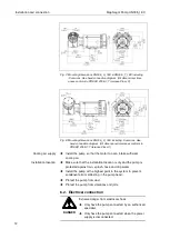
Fig. 8: Mounting dimensions UN035._S_I EX including .9 versions. See
head connection diagram. (All dimensional tolerances conform to
DIN ISO 2768-1, Tolerance Class V)
Install the pump so that the motor fan can intake sufficient
cooling air.
Make sure that the installation location is dry and the pump is
protected against rain, splash, hose and drip water.
Install the pump at the highest point in the system to prevent
condensate from collecting in the pump head.
Protect the pump from dust.
Protect the pump from vibrations and jolts.
6.2. Electrical connection
DANGER
Extreme danger from electrical shock
Only have the pump connected by an authorized
specialist.
Only have the pump connected when the power
supply is disconnected.
Cooling air supply
Installation location

