background image

Diaphragm pump N 2400.15 


Transportation 

Translation of original Operating and Installation Instructions, english, KNF 308934-308937 09/18 

17 


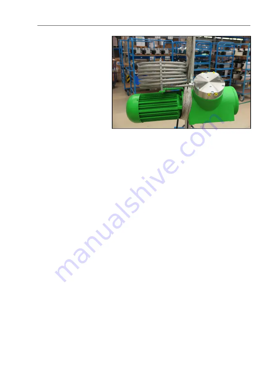
Fig. 5: 

2.  Fix the harness between compressor housing and motor (Fig. 

5)

3.  Make sure that the lifting load cannot be transferred from the 

belt to the pump connection. 

4.  Use a lifting device to lift the pump out of the packaging. 

5.  Place the pump carefully at the installation location. 

Summary of Contents for N 2400.15

Page 1: ...2400 15 TRANSLATION OF ORIGINAL OPERATING AND INSTALLATION INSTRUCTIONS ENGLISH DIAPHRAGM PUMP Note Before operating the pump and the accessories please read the operating instructions and pay attent...

Page 2: ...7 Installation and connection 18 8 Operation 25 9 Servicing 27 10 Troubleshooting 33 11 Spare parts and accessories 35 12 Returns 36 13 Health and safety clearance and decontamination form 37 KNF Neu...

Page 3: ...the pump Fail ure to do so many results in severe or potentially life threatening injury and or serious damage Customer specific project pumps pump models which begin with PJ or PM may differ from the...

Page 4: ...tion Instructions english KNF 308934 308937 09 18 Other information and symbols An activity to be carried out a step is specified here 1 The first step of an activity to be carried out is specified he...

Page 5: ...well as other pollutions The gas tightness of the connections between the application pipes and the pump or the pump connection must be checked regularly with leaky connections there is a danger that...

Page 6: ...losive atmosphere The pumps are not suitable for transferring Dusts Liquids Aerosol Biological and microbiological substances Fuel Explosive and combustible materials Fibers Oxidizing agent Foodstuffs...

Page 7: ...that the personnel has read and understood the Operat ing and Installation Instructions and in particular the Safety chap ter Observe the accident prevention and safety regulations when per forming a...

Page 8: ...leted machinery and are therefore to be regarded as not ready for use Partly completed machinery may not be commissioned until such time as it has been determined that the machine in which the partly...

Page 9: ...e free But KNF recommends checking the pump regularly with regard to conspicuous changes in noise and vibrations Only have repairs to the pumps carried out by the KNF Customer Service responsible Hous...

Page 10: ...l Diaphragm PTFE coated Reed valves valve stopper Stainless Steel Retainer plate Stainless Steel O ring FPM Pneumatic head connection Stainless Steel Tab 3 Pneumatic values N 2400 15 SPE Parameter Val...

Page 11: ...be ID 9mm N 2400 15 STE Tube ID 9mm Tab 7 Electrical data Parameter Value Electrical data See type plate pump Protection class Motor IP 55 Protection class Pump See Type plate pump Maximum permitted m...

Page 12: ...2400 15 STE See Fig 7 Chapter 7 1 Maximum permissible ambient relative humidity 80 for temperatures up to 31 C decreasing linearly to 50 at 40 C Max altitude of site m above sea level 2000 Gas tightne...

Page 13: ...ragm N 2400 15 SPE Design N 2400 15 STE Fig 2 Diaphragm N 2400 15 STE 1 Pneumatic pump inlet 2 Pneumatic pump outlet 3 Connection water cooling 4 Interstage cooler 5 Fan cover 6 Motor 7 Terminal box e...

Page 14: ...vapors The elastic diaphragm 4 is moved up and down by the eccentric 5 and the connection rod 6 In the downward stroke it aspirates the gas to be transferred via the inlet valve 2 In the upward stroke...

Page 15: ...d injure people If necessary use suitable aids harness lifting device etc If necessary wear proper personal protective equipment e g safety gloves safety shoes CAUTION Danger of injury due to sharp ed...

Page 16: ...N 2400 15 16 Translation of original Operating and Installation Instructions english KNF 308934 308937 09 18 Transportation with harness Fig 4 Position of the harness exemplary 1 Pull the harness thr...

Page 17: ...ish KNF 308934 308937 09 18 17 Fig 5 2 Fix the harness between compressor housing and motor Fig 5 3 Make sure that the lifting load cannot be transferred from the belt to the pump connection 4 Use a l...

Page 18: ...onditions described in Chapter 4 Technical Data Observe the safety precautions see Chapter 3 7 1 Installation of the pump Before installation store the pump at the installation location to bring it up...

Page 19: ...lly malleable objects placed in the immediate ambient of the hot pump parts head motor Make sure that the installation location is dry and the pump is protected against rain splash hose and drip water...

Page 20: ...contact and intrusion of foreign mat ter 7 2 Electrical connection DANGER Extreme danger from electrical shock Only have the pump connected by an authorized specialist Only have the pump connected whe...

Page 21: ...nal box cover 3 Connect the earth ground wire to the motor 4 Connect the mains cables according to the operating instruc tion of the motor Set the direction of rotation in accordance with the arrow on...

Page 22: ...s the direction of flow CAUTION Risk of injury due to mixing up suction and pressure side Mixing up the suction and pressure side can lead to the rupture of connected components on the suction and pre...

Page 23: ...life of the diaphragm especially at high pressures or high am bient temperatures Recommended parameters Parameter Value Water temperature 5 C to 30 C Water flow quantity l min 1 0 Tab 12 Mounting dim...

Page 24: ...lation Instructions english KNF 308934 308937 09 18 Fig 9 Mounting dimensions pump series N 2400 15 STE All dimensional tolerances conform to DIN ISO 2768 1 Tolerance Class V Operate the water connect...

Page 25: ...pumps are not used improperly see Chapter 2 2 Observe the safety precautions see Chapter 3 The pumps are intended for installation Before putting them into service it must be established that machiner...

Page 26: ...spheric pressure The pump may not start up against pressure or vacuum during switch on This also applies in operating following a brief power failure If a pump starts against pressure or vacuum it may...

Page 27: ...pump under atmospheric conditions some minutes with air or if necessary for safety reasons with an inert gas prior to switch off to increase the service life of the diaphragm Drain the media safely 9...

Page 28: ...e measures CAUTION Danger of burns from hot pump parts The pump head or motor may be hot even after the pump has been shut off Allow the pump to cool after operation Spare part Position Quantity Diaph...

Page 29: ...o mark the union nuts Fig 2 7 according to Fig 11 and loosen them 3 Mark the position of head plate 4 intermediate plate 14 and housing 13 relative to each other by a drawing line with a felt tip pen...

Page 30: ...3 Remove diaphragm 8 4 Only 13 Remove the O ring 12 from the housing 13 5 Only 13 Remove the O ring 11 from the diaphragm support 9 6 Inspect all parts for dirt and clean them if necessary There migh...

Page 31: ...the second pump head Changing reed valves 1 Remove the two O rings 7 from the intermediate plate 14 2 Undo the two screws 2 and remove valve limiters 3 and reed valves 5 from the intermediate plate 14...

Page 32: ...308934 308937 09 18 6 Turn the fan to check that the pump rotates freely 7 Carry out steps 1 to 6 for the second pump head 8 Remount fan cover Fig 2 7 9 Remount the pneumatic connection or the interst...

Page 33: ...the pump under atmospheric conditions some minutes with air if necessary for safety reasons with an inert gas Diaphragm or reed valves are worn Replace diaphragm and reed valves see Chapter 0 Tab 16 F...

Page 34: ...p to KNF Customer Service contact data see www knf com 1 Flush the pump under atmospheric conditions some minutes with air if necessary for safety reasons with an inert gas to free the pump head of da...

Page 35: ...y 13 11 047372 O ring only 13 12 047373 Tab 18 according to Fig 10 N 2400 15 STE Spare part Position Order No Diaphragm 10 118095 Reed valve 5 003475 Valve stopper 3 001714 O ring 7 002458 O ring only...

Page 36: ...and decon tamination form For optimal processing of a return a copy of this declaration should be sent in advance via e mail regular mail or fax to KNF Customer Service contact data see www knf com In...

Page 37: ...2400 15 Health and safety clearance and decontamination form Translation of original Operating and Installation Instructions english KNF 308934 308937 09 18 37 13 Health and safety clearance and decon...

Page 38: ......

Page 39: ......

Page 40: ...KNF worldwide Find your local KNF partner on www knf com...

Reviews: