background image

PWR

           KMB systems

The insulation voltage and the certified overvoltage class are not sufficient for the required overvoltage
category. This concerns the isolation of the power circuit compared to the output terminals (DC output
voltage, external backup source and signalling).

Additional measures:

The input voltage of the power module is limited to 300V CAT II with an additional voltage limiter while the
device is operated in a 300V CAT IV environment.
The voltage limiter is designed with two varistors that are connected in parallel to the input terminals (ter-
minals L and N or L1, L2, L3 and N against PE). The required test 6kV / 3kA—1.2 / 50μs was performed
and the varistors are suitable for use in a 300V CAT IV environment. The supply voltage is protected by
an external fuse with the specified value and breaking capacity, type: aM 2A 500V / 120kA  10x38mm.

When using two varistors in parallel, it is ensured that the limit value of the overvoltage category is ob -
served even if one varistor is defective (in case of one fault).

Operational risk with additional measures:

As a consequence of the protective measures taken, no operational risk arises.

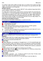
4. Used symbols

Warning! Electric shock hazard!
Danger! Read the instructions!
The CE marking guarantees compliance with European directives and EMC regulations.

IP20

Anti-touch protection, anti-ingress of objects larger than  12.5mm,

without water protection.
This product must not be disposed of in a household waste bin but must be disposed of in such a 
way as to ensure its environmentally friendly recycling.

~

 / 

=

Alternating voltage, AC / direct voltage, DC.

5. Installation

 The person installing the system is responsible for safety of whole system containing the PWR.

Installation:

PWR is installed on DIN 35 rail in standard manner. Natural circulation of the air in the cubicle should be
ensured. Clarence of 50mm above and below PWR should be maintained.

 No heat sources should be located bellow PWR.

Supply voltage:


Supply voltage have to be connected to L, N terminals resp. L1, L2, L3, N terminals through circuit

breaker. CB should be located in close distance to PWR on accessible place for operator. Circuit breaker
should be properly marked. Proper fuse and disconnecter housing should be used (i.e. OPVP10 and fuse
PVA10 2A aM, 500V/120kA, 

10x38mm, see accessories), Alternative fuses should be consulted with

producer.
Terminals accepts 0,2÷4mm

2

 (24÷12AWG) wires, tightening torque 0,5÷0,6Nm.

  Protection Earth, PE terminal,

have to be connected with 4mm

2

  (12AWG) wire directly without

circuit breaker. Tightening torque 0,5÷0,6Nm.

 Supply inputs are polarity free.

Output voltage:

Output voltage is on terminals   + and -. Terminals are doubled for easier wiring. Terminals accepts
0,2÷2,5mm

2

 (24÷14AWG) wires, tightening torque 0,5÷0,6Nm.

 Conductors of proper cross-section have to be used depending on current and voltage loss.

3

Summary of Contents for PWR 1A 60W 24V

Page 1: ...this manual may not always contain the latest information In this case please contact us or use the latest version of the operating instructions available on our website http www kmb cz Scope of delivery PWR unit including connector Operating Instructions Warranty card Certificates Optional accessories external battery CTL 7 12 12V 7Ah lifetime 10 years circuit breaker fuse switch OPVP10 OEZ 41013...

Page 2: ...tion against wrong connection of the accumulator and against total discharge of accumulator Cooling is provided by natural flow of the air Fan less 2 Safety instructions Danger of electric shock Do not open the device Follow the operating instructions Keep the operating instructions together with the device Ensure that the device works only in perfect and original condition in the upright position...

Page 3: ...rotection anti ingress of objects larger than 12 5mm without water protection This product must not be disposed of in a household waste bin but must be disposed of in such a way as to ensure its environmentally friendly recycling Alternating voltage AC direct voltage DC 5 Installation The person installing the system is responsible for safety of whole system containing the PWR Installation PWR is ...

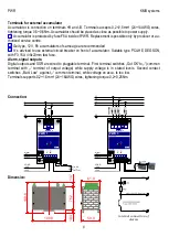
Page 4: ...outputs and SSR are wired to pluggable terminal First terminal switches Out OK to common terminal with terminal of output voltage while supply voltage is in stated levels Second contact switches Batt Low against common terminal while voltage on accu Is too low Terminals supports 0 2 1 5mm2 24 16AWG wires tightening torque 0 2 0 25Nm Connection Dimension 4 internal connection of alarms 109 8 59 0 1...

Page 5: ... limited to 0 75A Output voltage is based on charge level of accumulator see charts Operator have to Operator must ensure that drawn power don t cross limits stated in thermal chart This model can be operated also without accumulator In such a case output voltage will be equal to max imal voltage of the output see specifications Operation of PWR from line to line voltage in 3 400 230V networks onl...

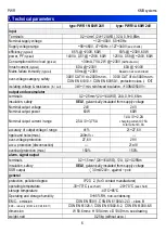
Page 6: ...y SELV galvanically insulated from supply voltage Nominal output voltage 24V 24V Nominal output power 60W 60W Nominal output current range 2 5A 0 3 75A 1 4A 0 2 2A charging current 0 75A total current 3 0A accuracy of output voltage range 1 21 27 6V ripple and noise max 240mVP P over voltage protection 27 6V 29V accu protection disconnection 21 1V overload protection max 150 150 alarm signal outpu...

Page 7: ...y voltage Nominal output voltage 24V 24V Nominal output power 60W 60W Nominal output current range 1 45A 0 3A 0 4A 0 1 1A charging current 0 75A accuracy of output voltage range 1 21 27 6V ripple and noise max 240mVP P over voltage protection 27 6V 29V accu protection disconnection 21 1V overload protection max 300 300 alarm signal output Terminals 0 2 1 5mm2 24 16AWG 12A 0 2 0 25Nm Insulation saf...

Page 8: ...40 480 0 25 50 75 100 125 PWR 1N 60W 24V U V P 80 120 160 200 240 280 320 360 400 440 480 0 25 50 75 100 125 PWR 1A 60W 24V U V P 120 160 200 240 280 320 360 0 25 50 75 100 125 PWR 1N 60W 24V U V P 120 160 200 240 280 320 360 0 25 50 75 100 125 PWR 1A 60W 24V U V P 80 120 160 200 240 280 320 0 25 50 75 100 125 PWR 3N 60W 24V U V P 80 120 160 200 240 280 320 0 25 50 75 100 125 PWR 3A 60W 24V U V P ...

Page 9: ...2 2 5 3 0 0 2 0 4 0 6 0 8 1 PWR 1A 60W 24V 230 23 3 120 23 3 230 25 120 25 230 27 2 120 27 2 Iz A Ia A 40 30 20 10 0 10 20 30 40 50 60 70 80 0 25 50 75 100 125 PWR 1N 60W 24V t C P 40 30 20 10 0 10 20 30 40 50 60 70 80 0 25 50 75 100 125 PWR 1A 60W 24V t C P 40 30 20 10 0 10 20 30 40 50 60 70 80 0 25 50 75 100 125 PWR 3N 60W 24V t C P 40 30 20 10 0 10 20 30 40 50 60 70 80 0 25 50 75 100 125 PWR 3A...

Page 10: ... a product failure a claim must be made with the supplier or the manufacturer at KMB systems s r o Dr M Horákové 559 460 06 Liberec 7 tel 420 485 130 314 fax 420 482 736 896 e mail kmb kmb cz internet www kmb cz The product must be properly packed in such a way as to avoid damage during transport The product must be provided with a description of the defect her speech Entitlement to warranty servi...

Reviews: